– — .-. … .
We look at two ways to generate Morse code, then use the code to open and close a telegraph sounder.

Lead Image © Jana Guothova, 123RF.com
We look at two ways to generate Morse code, then use the code to open and close a telegraph sounder.
My first exposure to Morse code [1] was 15 years ago at an amusement park. I stumbled into a small exhibit, complete with a ticket agent mannequin that, despite his rather stiff appearance, was managing to send Morse code on an authentic telegraph key and sounder. That exhibit always stuck in the back of my mind, and in the years since, I've had the opportunity to recreate it a few times.
My original build was for the Interurban Museum in Plano, Texas, where I was a volunteer. Although the Texas Electric Railway never used telegraph equipment for communication, the museum had a small display about it. I thought it'd be great for someone to be able to "talk back" to the telegraph exhibit, so I started figuring out how to do that, with little more than a desired outcome and no idea of the path to take.
The development platform available to me at the time was an Atari 800XL [2], so using my newly learned skills in BASIC, I wrote a program to translate characters to their equivalent dots and dashes.
Next, I dug into the Atari's programming manual and found the codes that control the audio cassette tape recorder, which was used as the storage medium, as well as an audio output. I had the official Atari-branded model that plugged into the peripheral bus, so I didn't have to use an external audio cable.
By sending control commands to the tape directly, I was able to record my Morse code messages as data "marks" and omit the "spaces." That isn't to say I eliminated the time between dots and dashes, but I fooled the tape recorder.
Data on the Atari tape was either a "mark," a tone at 5,327Hz representing a binary 1, or a "space," a tone at 3,995Hz representing a binary 0. In a normal setting, this data was recorded on the tape at the blazing rate of 600 baud. To make the Morse code tape, I told the tape recorder to generate marks only and started and stopped the generator with timing from my original program.
The tape that came out of the Atari that Saturday afternoon sounded just like the code tapes I listened to so often when studying to pass my ham radio Morse code test. Now the challenge was to convert the tone into a form that could open and close a telegraph sounder. Enter the LM339.
The LM339 [3] is a quad comparator integrated circuit. Each comparator has a positive and a negative input, but this is somewhat deceptive, in that both inputs expect positive voltage. When the positive input is receiving a higher voltage than the negative input, the output of the comparator connects to ground. Otherwise, the output is open.
A signal transistor controlled by the comparator switches the actual load, a small signal relay. This in and of itself produces a nice clicking sound very similar to a telegraph sounder. Looking back, the transistor was probably enough to switch the telegraph sounder directly, but I wasn't sure, and I certainly understood the switches of a set of relay contacts. I also reasoned that the telegraph could then have its own power source, while my circuit remained independent.
To get the telegraph to operate, you just had to play the tape! The circuit decoded the tones and clicked the relay, which in turn clicked the sounder in the display. I took great pride in crawling under the exhibit at the end of each weekend to rewind the tape.
Fast forward to today, when the telegraph project suddenly reappeared. I was contacted by a friend that wanted an automated telegraph display for a local train show. Remarkably, he had an MP3 player with recordings of Morse code tones. I called my dad, who had been a brilliant consultant the first time around, and we rehashed the circuit design. Figure 1 shows what we came up with.
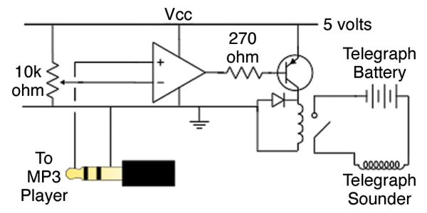 Figure 1: The tone decoder circuit. The circuit relies on the voltage generated by the tone and lack thereof when the audio source is silent.
When my friend received the design, he promptly procured the components (Figure 2). He reported back the following day that it "sort of worked." After a few rounds of testing with a multimeter and step-by-step tests, we determined that the voltage arriving from the MP3 player wasn't high enough to trigger the comparator, even with the sensitivity adjustment at its minimum.
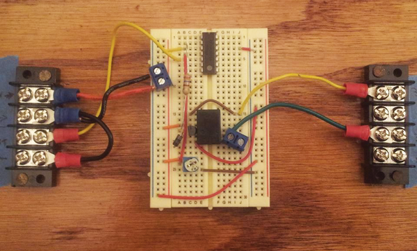 Figure 2: The finished comparator circuit mounted on scrap plywood. Note the added barrier strips for connections to power and telegraph equippment.
In retrospect, my tape recorder was designed to drive an 8-ohm speaker directly. I didn't know it at the time, but plenty of voltage was coming from that device to trigger the detector. I solved the weak signal problem by sending my friend back to the parts store to pick up an inline headphone amplifier. That did the trick. It also has a speaker built in, which has the added advantage of being able to play the tones directly for Morse code via wireless radio.
Pages: 6
US / Canada
UK / Australia

Build a secret message encoder with Morse code.
The accessories, signals, and towns come to life on my Lionel train layout with the help of sensors, detectors, lots of relays, and Linux control software. The trains, though, remain strictly under human control. This year that's about to change!

Thanks to the avNav free software, the Raspberry Pi becomes a control center for electronics on a yacht.

As the Raspberry Pi finds its way onto more and more workbenches, new opportunities arise not only to transfer data from electronic projects to a local network or the Internet but also to provide options for feedback and control.

Create your own sail boat and steer it with a low-cost remote control.

Price $15.99
(incl. VAT)