Connecting your Raspberry Pi with a real-time clock
Modifying the Adafruit DS1307
One very important thing to remember about the Raspberry Pi is that all the GPIO inputs and outputs are 3.3V and are not tolerant of 5.0V. You will burn out pins on the Raspberry Pi if you connect 5.0V outputs to them. The Adafruit DS1307 is a 5V board. How do you get around this?
The Raspberry Pi has a 5V power supply pin (pin 2 on the P1 header on the Raspberry Pi), so you can connect that pin up to the DS1307. The issue is the SDA and SCL pins for the I2C interface. Remember that these two lines are open-drain lines. The problem for the Raspberry Pi is that SDA and SCL are connected to two 2k2 pull-up resistors, and these resistors are connected to the 5.0V line. You can't connect these lines to the Raspberry Pi without modifications.
The unmodified DS1307 is shown in Figure 2. R2 and R1 are the pull-up resistors on the SDA and SCL line to 5V. You need to clip those resistors because the Raspberry Pi already has pull-up resistors on SDA and SCA to 3.3V. To clip the resistors, take a pair of wire clippers, snip the wire in the middle of the lead (so you can solder them together in the future if needed), and bend the resistors up, as in Figure 3.
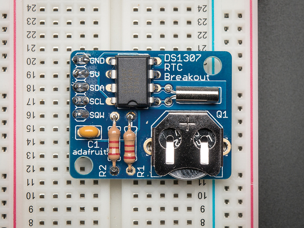 Figure 2: Unmodified DS1307 board.
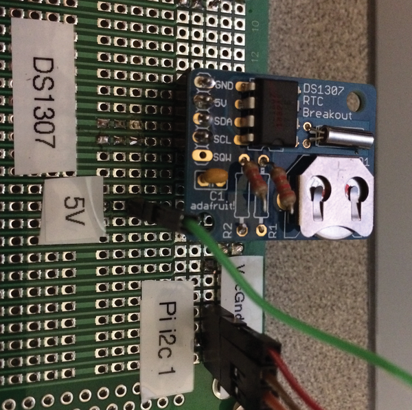 Figure 3: Modified DS1307 board with resistors R2 and R1 disconnected.
Now you can connect your DS1307 board to your Raspberry Pi 5V (see the green wire in Figure 3).
Hooking Up Your Raspberry Pi to I2C
After you have clipped the resistors on the DS1307 board, it is time to hook it up to the Raspberry Pi. I used a prototyping board, but a breadboard would also work just fine. The Raspberry Pi/DS1307 circuit is shown in Figure 4, and the Rasp Pi GPIO pinout is shown in Figure 5.
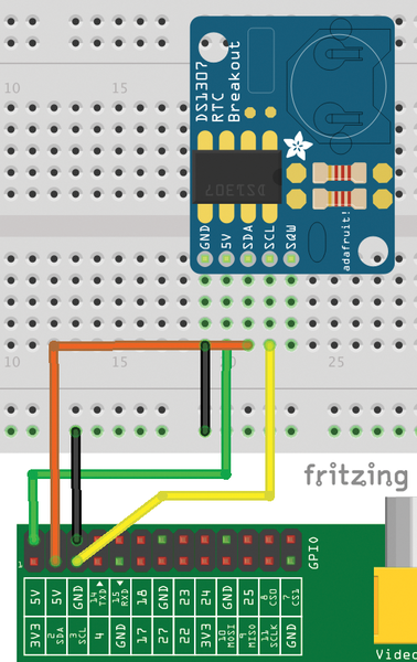 Figure 4: Connecting the Rasp Pi to the DS1307 RTC.
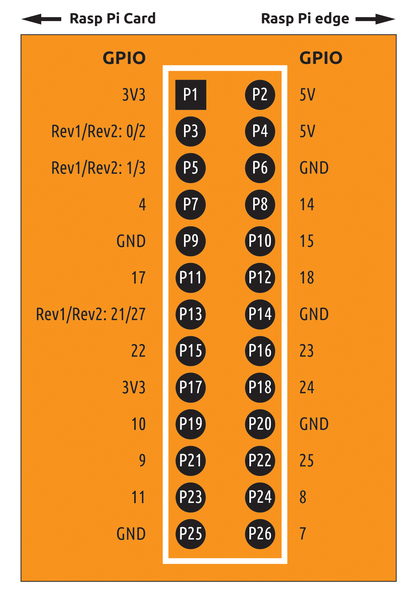 Figure 5: Raspberry Pi GPIO. Notice that the GPIO pin numbers (the outside labels) and the header pin numbers (the "P" numbers) are different. For example, GPIO 4 is header pin 7. In these instructions, I refer to the header pin numbers.
To begin, hook up four lines from the Rasp Pi to the DS1307: Connect header pin 2 (5.0V, green wire) on the Rasp Pi GPIO to the second pin (marked 5V) on the DS1307; next, hook up header pin 6 (black wire) on the GPIO to the first pin (marked GND) on the DS1307. In Figure 4, I did this by linking from the header pin to the breadboard power rail (-- GND) with one black wire, and then linking from the power rail to GND on the DS1307 with a second black wire.
To continue, you connect header pin 3 (SDA, orange wire) on the GPIO to the third pin on the DS1307 (marked SDA) and header pin 5 (SCL, yellow wire) on the GPIO to the fourth pin on the DS1307 (marked SCL). Make sure you have clipped those resistors on the DS1307!
Hook it up, check it twice (see the box "Checking It Twice"), then apply power. When the Raspberry Pi has boot up, try:
sudo i2cdetect -y 1
You should see the device at 0x68 in the result, as you did in a previous section.
Checking It Twice
Always check your connections twice before applying power to your setup. Use a multimeter to make sure your lines are connected and to the right place. You can get a multimeter at any hardware store or Radio Shack. My well-used multimeter is shown in Figure 6.
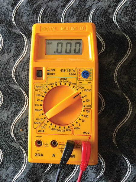 Figure 6: My well-worn multimeter has survived many projects.
With the power to the Pi and DS1307 disconnected, use the resistance measurement on the multimeter to make sure all the lines on the DS1307 are connected to the proper pins on the Pi, as in Figure 4. A resistance of 0 (zero) means the lines are connected, and a higher resistance value means it is not connected. Check for shorts (0 resistance), especially between 3.3V and ground.
« Previous 1 2 3 4 Next »
Buy this article as PDF
Pages: 5
(incl. VAT)
Buy Raspberry Pi Geek
US / Canada
UK / Australia
Related content
-
Comparison of four real-time clocks

In the previous column we looked at the DS1307 real-time clock and the I2C bus. This month, we look at three more real-time clocks and compare all four.
-
Automated plant watering with Arduino

House plants are fairly self-sufficient, but they do need certain care from people to survive. With a few Arduino sensors and a little programming, you can take the guesswork out of watering your plants.
-
Connecting a weather station to your Arduino
After losing one weather station to tropical winds, the author reboots and designs a PCB that connects to an Arduino and monitors weather instruments.
-
Uninterruptible power supply for the Raspberry Pi

A sudden loss of power can create critical problems for many applications. To avoid such outages, the Raspberry Pi has a proper uninterruptible power supply.
-
Build a Raspberry Pi-based backup device

With some creativity and a little scripting, you can easily turn your Raspberry Pi into an effective backup device.
