Building a Motion Detector using Scratch GPIO server
Configuring Pins and Lighting LEDs
As I work toward the motion detector, I'll first show how to control an LED through the GPIO server so that you can see the steps necessary to configure and control a pin. For the simple circuit, connect an LED to pin 15 through your breadboard. Make sure to use a resistor to protect the LED.
The Scratch GPIO server uses the BCM numbering system to address pins, rather than the physical pin location. Refer to Figure 2 to identify the pin numbers. BCM refers to the chip maker, which is Broadcom. The BCM numbering does not follow a human-friendly pattern, which is why you should always reference a pin diagram.
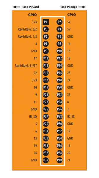 Figure 2: BCM pin numbers are labeled "GPIO" here.
Before you can turn the LED on or off, you need to configure it at the start of the project with a broadcast message. The broadcast(config15out) block accomplishes the goal. The command to configure the pin consists of three parts (config+pin number+configuration option).
For this example, the only configuration option I'm using is in or out, but there are others. Using in or out sets the specified pin number as either an input or an output. Inputs take sensory information from the physical world and send it to Scratch. An example is the PIR sensor that I'll use later in this project. Outputs send information from Scratch to the physical world, such as lighting an LED.
Using the GPIO server, a pin can be configured as either input or output, making it critically important to your project that you specify the configuration before you attempt to use it.
You can experiment with the commands by turning an LED on and off. Figure 1 shows a script that turns the LED on and then off, which is happening with the gpio15on and gpio15off broadcast messages. When you control a pin, the message consists of three parts (gpio+pin number+setting). My example uses on and off as the settings, but you can also substitute low and high, respectively.
Adding a PIR Sensor
The PIR sensor detects movement. The sensor has three labeled pins. Connect the sensor pin labeled GND to the ground on the Pi. Connect to pin labeled OUT to pin 21.
The sensor pin labeled VCC can be connected to a 5V or 3.3V pin on the Raspberry Pi, depending on the power requirements of your sensor (Figure 3). My sensor happens to work with either. Refer to the pin diagram in Figure 2 to find the power pins. The 5V and 3.3V power pins supply power to the sensor continuously.
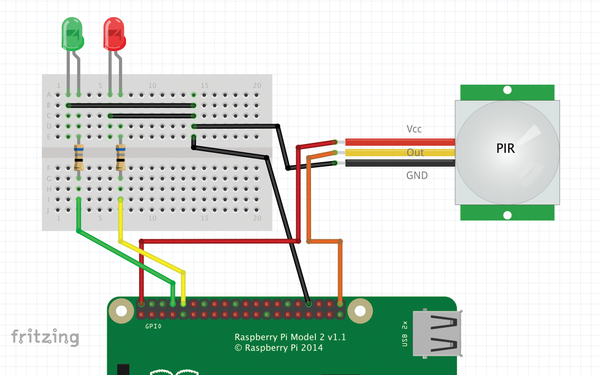 Figure 3: Diagram of the wiring between the PIR sensor, the Rasp Pi, and the LEDs. (Fritzing)
To detect movement, you need to monitor the OUT pin of the sensor, which should be connected to pin 21 on the Raspberry Pi. As part of the project initialization, set pin 21 as an input. Figure 4 shows the initial configuration for all the pins in the project. Pins 14 and 15 are configured as outputs. Connect pin 14 to a green LED via a resistor and connect pin 15 to a red LED through a resistor. The LEDs provide a visual indicator to help you see if motion is detected; red will signal motion, and green will signal no motion.
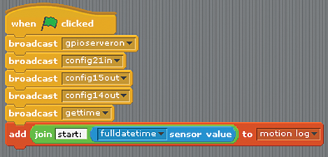 Figure 4: Script to configure the initial values for the motion detector project.
« Previous 1 2 3 4 Next »
Buy this article as PDF
Pages: 4
(incl. VAT)
Buy Raspberry Pi Geek
US / Canada
UK / Australia
Related content
-
Stop-motion animation

Stop-motion animation doesn't require expensive cameras and movie editing software. With Scratch and a Pi camera, you can become your own director, producer, and publisher.
-
Creating a multiplayer quick-reaction game

The quick-reaction game provides an introduction to building simple circuits with the Raspberry Pi and controlling those circuits with ScratchGPIO, an advanced version of Scratch.
-
Diving Deep
The past year has seen a continued emphasis on STEM (science, technology, engineering, and mathematics) education in English-speaking countries.
-
PHP on Raspberry Pi

Getting started with PHP on Raspberry Pi is easy. We show how to build a simple PHP app to control an LED.
-
Building a video-enabled nest box

We show you how to build a completely wired nest box that charts the movements of nesting birds and delivers photo images of hatchlings.
