Capemgr keeps track of the BeagleBone Black's expansion boards, known as capes
Controlling Capemgr
When booting a BBB system without any capes attached, many of the pins available via the P8 and P9 connectors are already allocated for specific purposes, because some pins are physically wired to specific lines on the board, and some are muxed by the device tree. Figure 2 shows which pins are already allocated and the signals that are available on them. Some of the used pins provide power or addressing signals that can't be muxed differently to serve a different purpose. Other pins in use belong to the built-in capes (e.g., eMMC, HDMI) that are detected and configured via dynamically applied overlays at boot.
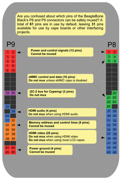 Figure 2: Pins in use by default on the BeagleBone Black.
But, how are the capes attached to the BBB identified, and what part of the kernel loads the device tree overlays for those capes? Most importantly, how can you control this behavior? The answer to all of these questions is the Capemgr subsystem of the kernel. Capemgr is responsible for detecting any capes connected to the BBB and handling requests that load overlays.
Capemgr exposes its userspace interface through the /sys/devices/bone_capemgr.* directory via the sysfs filesystem. The slots file within this directory is used to interact with Capemgr. When Capemgr loads an overlay, it allocates the overlay to a "slot" within Capemgr. To determine which Capemgr slots currently contain an overlay, cat out the slots file. For a BBB in a default configuration without any capes connected, the slots output looks like Listing 2.
Listing 2
slots Output
user@beaglebone:~#  cd /sys/devices/bone_capemgr.*
user@beaglebone:/sys/devices/bone_capemgr.8# cat slots
0: 54:PF---
1: 55:PF---
2: 56:PF---
3: 57:PF---
4: ff:P-O-L Bone-LT-eMMC-2G,00A0,Texas Instrument,BB-BONE-EMMC-2G
5: ff:P-O-L Bone-Black-HDMI,00A0,Texas Instrument,BB-BONELT-HDMI
Figure 3 identifies what each field of the slots output means. The slot number is used by Capemgr to identify what device tree overlays are currently loaded. The first four slots (0-3) are reserved for overlays associated with capes that have been physically plugged in to the BBB. The I2C bus address is a hexadecimal byte used by capes to request that the cape be placed in a particular slot.
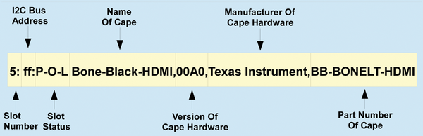 Figure 3: The various fields of Capemgr slots output.
Overlays that are loaded and not associated with an attached cape board (e.g., those manually loaded from userspace or associated with the built-in HDMI and eMMC capes) will have a listed I2C bus address of ff.
The slot status describes the current state of the slot. For more information on the slot status field, see the "Understanding the Slot Status Field" box. The remaining fields are specified as properties within the device tree node for the overlay. They describe the name of the device, its version and manufacturer, and which overlay is associated with the hardware.
Understanding the Slot Status Field
The slot status field has five characters that describe the current state of a particular slot on the Capebus. Each character position in the slot status field represents a state that the slot is in and is either a letter (state is active) or a dash (state is not active). The five states are, from left to right in the slot status field, "P" (slot has been probed for a cape), "F" (probing failed for this slot), "O" (an override has placed the cape in this slot), "l" (cape is still being loaded), and "L" (cape loading has completed).
To load an overlay manually from userspace, the overlay must be a compiled .dtbo file that is located in the firmware directory of the root filesystem. The part number associated with the overlay (not the full file name of the .dtbo file) is echo'd into the slots file to load the overlay. The Capemgr will examine each .dtbo file within the firmware directory to find the overlay associated with that part number. If a .dtbo with that part number is found, that .dtbo file is loaded. For example, to load the overlay file MY_OVERLAY-00A0.dtbo, which is located in the firmware directory, use the following command:
user@beaglebone:~# sudo echo MY_OVERLAY > /sys/devices/bone_capemgr.*/slots
Three kernel command-line options control the behavior of Capemgr at boot. These options are passed to the kernel by specifying them within the U-Boot [5] bootloader's uEnv.txt configuration file. The first option is capemgr.enable_partno, which explicitly loads the overlay for one or more capes that have a specific Capebus slot allocated for them in the device tree.
The second option is capemgr.disable_partno, which forces Capemgr not to load an overlay for a cape that is physically present. The third is capemgr.extra_override, which is similar to capemgr.enable_partno but is used to load overlays for capes that do not have a specific Capebus slot allocated to them. Unless you know what you are doing, avoid using the extra_override option. You can potentially load an overlay into the wrong slot that way.
As an example, consider the BBB's built-in HDMI cape. The device tree specifies two nodes for this cape: one node for a "full HDMI cape" that provides both audio and video data (BB-BONELT-HDMI) and one node for a "video-only HDMI cape" that provides only video data (BB-BONELT-HDMIN). Each of these nodes references a different overlay.
Capemgr attempts to load both of these overlays automatically because the device tree nodes for the cape specifically request that both always be loaded during kernel boot. Because both of these overlays request exclusive usage of the same resource (the pins that provide the video signal), only one can be loaded at any time.
The full HDMI cape overlay is given a higher priority by the device tree, so Capemgr will attempt to load it first before loading the video-only HDMI overlay. If Capemgr successfully loads the full HDMI overlay, then its attempt to load the video-only HDMI overlay will fail.
It is sometimes desirable to use the video-only HDMI overlay, rather than the full HDMI overlay. For example, the four McASP0 pins that carry the audio signal in the full HDMI overlay can be muxed into an additional SPI channel (SPI1) or GPIO signals, which might be more important to a project than having HDMI audio. Because the full HDMI overlay always loads before the video-only HDMI overlay, Capemgr must be told to skip loading the full HDMI overlay. This is done by adding the following command-line option to your kernel:
capemgr.disable_partno=BB-BONELT-HDMI
To disable the HDMI cape completely by not loading either the full or the video-only HDMI overlays, add the following command-line option to your kernel:
capemgr.disable_partno=BB-BONELT-HDMI,BB-BONELT-HDMIN
By not loading both HDMI overlays, you completely disable the built-in HDMI cape, which frees up 24 pins on the P8 and P9 connectors that can now be muxed into a combination of UARTS and GPIOs. Note that disabling only BB-BONELT-HDMIN (the video-only HDMI overlay) will have no effect because the higher priority full HDMI overlay will still be loaded.
Conclusion
The device tree and Capemgr give you a great deal of control over the BBB when configuring the system for custom interfacing projects. Knowing which pins of the BBB are in use, and understanding how to change their usage to suit your needs, will help you make the best use of the platform for your specific project.
Infos
- TI Sitara AM335x Technical Reference Manual: http://www.ti.com/lit/ug/spruh73i/spruh73i.pdf
- BeagleBone Black system reference manual: https://github.com/CircuitCo/BeagleBone-Black/blob/master/BBB_SRM.pdf?raw=true
- Device tree data structure: http://www.devicetree.org
- Capemgr subsystem: http://elinux.org/Capemgr
- U-Boot bootloader: http://www.denx.de/wiki/U-Boot
« Previous 1 2 Next »
Buy this article as PDF
Pages: 6
(incl. VAT)
Buy Raspberry Pi Geek
US / Canada
UK / Australia
Related content
-
HDMI and the BeagleBone Black Multimedia Environment

You'll need a little troubleshooting and some basic knowledge of HDMI if you plan to use your BeagleBone Black for multimedia applications.
-
New Products
What's new in the SBC, IoT, and maker realm.
-
Accessing Raspberry Pi services via the Internet
The virtual private network (VPN) from Weaved offers an elegant and secure solution for creating external access to services running on a Raspberry Pi inside a home network. Besides offering great functionality, Weaved is available with a free account.
-
Raspberry Pi 3 Model B in detail

The Raspberry Pi 3 changes the game with its fast, 64-bit CPU and support for WiFi and Bluetooth.
