Frequently, the private place you have found for conducting a video chat via a mobile device does not provide a high enough WiFi data transmission rate for smooth and consistent transmission. This problem can arise in multistory apartment buildings with reinforced floors or in a remote corner of your yard. Reception issues are caused either by insufficient signal strength or getting tangled in the channel underbrush of neighboring WiFi networks whose access points unfortunately use channels that overlap that of your network.
Data Rates
The WiFi standard currently most often used is IEEE 802.11g, and it is the basis of the discussion in this article. This standard specifies a data rate of 54Mbps when fully utilizing 20MHz channel spacing. In practice, an actual effective data rate of only about 22Mbps can be obtained, even under ideal conditions.
This effective data rate is further reduced if neighboring WiFi cells either completely or partially (in 5MHz segments) overlap with the channel area of your own access point. If the reception quality at either endpoint of the wireless link falls below a threshold, which is specific to each receiving device, then the data rate deteriorates significantly. The reception performance in open space between the access point and the receiving unit is approximately inversely proportional to the square of the distance.
An even more dramatic effect on reception quality can be observed in buildings constructed with metal components extending over large areas, such as steel reinforced floors. These components act as reflectors, and reception performance may drop practically to zero merely by moving around a couple of feet. This effect can be due to destructive interference of radio waves that cause the signal to fade or to simple obstruction of the receiver.
Although you may be able to come to an agreement with your neighbors on the choice of WiFi channels, the realities of physics do not allow for negotiation with buildings and distances. (See the box "Why Not Use a Repeater?")
WiFi repeaters appear to offer an easy workaround to dead or weak reception areas. The repeaters act as separate access points that have the same transmission and security settings as the primary access point. However, the data rate observed by the receiver is actually reduced by about half because a repeater has to communicate via radio signal with both the receiver and the primary access point. For the 801.11g standard, this means the data rate is reduced to about 11Mbps.
This approach only works when there are no channel issues with neighboring WiFi networks and the transmission power of the primary access point at the repeater is such that the signal received by the repeater exceeds the repeater's receiving threshold for the maximum data rate. Otherwise, each additional repeater quickly drives the effective data rate into single-digit territory.
Access points that have been connected to one another via an Ethernet backbone offer a much better solution. This setup ensures that the data is transmitted only once between the receiver and the particular access point with which the client software has registered.
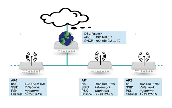
In this solution, each access point obtains its own IP address. To simplify network configuration, a network bridge couples the wireless and wired LANs directly inside the link layer (i.e., OSI Layer 2). Figure 1 displays the schematic for this network structure.
 Figure 1: A schematic representation of the envisioned network structure.
In the solution here, the Rasp Pi's assume the role of access points that have been configured with identical SSIDs and security settings (e.g., using WPA2-PSK). The Rasp Pi's also take on the role of the network bridge. A separate network router provides all additional network services, including DHCP, DNS, or routing.
For this setup, you should assign static IP addresses for the network bridges. You also need to communicate the static IP address assignment to the DHCP server of the router by removing these IP address from the IP lease address range.
Planning the Frequencies
The IEEE 802.11b standard introduced a channel spacing of 5MHz for WiFi networks in the 2.4GHz band, which spans 2,400 to 2,484MHz. The channel spacing begins with channel 1, which has a center frequency of 2,412MHz and a bandwidth of about 22MHz. The downward-compatible successor 802.11g uses a similar schema. The difference is that the maximum data rate is already obtained by means of a signal bandwidth of just under 20MHz.
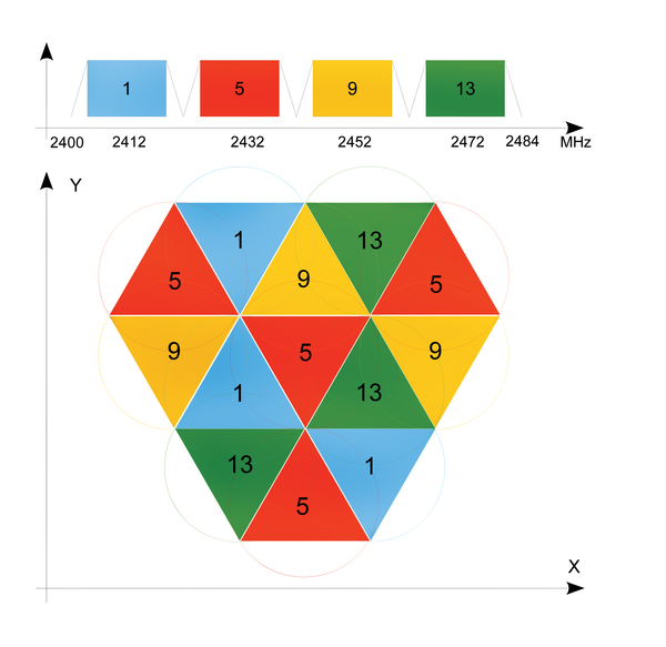
Because of the 5MHz channel spacing, the 20MHz channel bandwidth, and the overall 80MHz frequency block, only channels 1, 5, 9, and 13 are such that their bandwidths do not overlap and thus achieve the maximum data rate. Any time you choose a different channel, you obtain only three 20MHz channel aggregations that do not overlap, which leads to unused bandwidth at the lower and upper limits of the frequency block. Note that this discussion applies to Europe. The situation in the United States is slightly different, because only 11 channels are available.
Figure 2 shows the frequency ranges of the four channels at the top; the bottom shows how these channels are physically arranged to minimize mutual interference.
 Figure 2: At the top are the 802.11g channels in the 2.4GHz band. At the bottom is the optimal arrangement of broadcast cells, taking channel repetition into account.
When starting to plan frequencies, you should first obtain an overview of the WiFi neighborhood. This task is best done with a notebook computer because notebooks usually have superior receiving antennas. Linux lets you obtain this information by issuing the iwlist command from the wireless-tools package in the following format:
$ sudo iwlist wlan0 scanning
This command will give you a list of neighboring access points together with the channel used for each and the locally irradiated power. By repeating this procedure at various locations and observing variations in signal strength, you can get a rough estimate of the location of neighboring broadcast cells. At this point, you may be able to discuss optimal WiFi channel settings with your neighbors.