Build your own infrared camera
The unusual tonal values found in infrared photography offer a new perspective on the world. So-called IR cameras are costly, and converting a normal camera to function as an IR camera is expensive. The NoIR camera module for the Raspberry Pi [1] lets you build your own infrared camera.
Theory
Infrared light sits on the electromagnetic spectrum [2] right next to what humans call visible light (Figure 1). Depending on the source, visible light lies between 380 and 700 nanometers (nm). Infrared light occupies the region above and up to 1,400nm. This form of light remains invisible to the human eye, but photo diodes on the sensors of a camera are sensitive to it. As a result, electronics can make infrared light visible to humans.
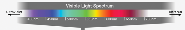 Figure 1: The infrared region of the light spectrum is not visible to the human eye even though it can be used to create impressive photographic effects. (Image source: Wikipedia)
[...]
Buy this article as PDF
Pages: 6
(incl. VAT)
Buy Raspberry Pi Geek
US / Canada
UK / Australia
Related content
-
New Products
What's new in the SBC, IoT, and maker realm
-
Working with the Raspberry Pi camera module

The amazing Raspberry Pi camera module opens into a whole new world of useful projects. We'll show you how to use the Pi camera for time-lapse photography, and we'll even help you set up a motion-detecting surveillance camera.
-
Extensions for the Raspberry Pi

The resourcefulness of private and commercial users has led to the creation of many practical and novel extensions for the Raspberry Pi. We provide an overview of some useful supplementary circuit boards.
-
Snapshot
The remarkable Raspberry Pi has spawned a myriad of supporting projects – Android apps, program libraries, specialized Linux distributions, and an assortment of hardware accessories. The rapid changes within these projects is testament to the excitement and enthusiasm that developers around the world have given to the Raspberry Pi.
-
Building a video-enabled nest box
We show you how to build a completely wired nest box that charts the movements of nesting birds and delivers photo images of hatchlings.
