Managing solar power systems with SunAir boards
AD Converters
Arduinos have 10-bit AD converters built in that take about 100 microseconds to read. They aren't great converters, but they are good enough for a number of applications. Because there it has only one AD converter and all the inputs are muxed together, you could run into a number of issues when taking samples too closely together. To get good, stable values, check out the excellent suggestions about measuring the temperature of beer (a noble endeavor) at Elco Jacobs' site [13]. The internal AD converters on the Arduino are sufficient for reading the photoresistors used by SunAir to track the sun, but because the Raspberry Pi has no built-in AD converters, SunAir includes a simple circuit to do this (Figure 5). The new SunAirPlus contains an excellent 12-bit, four-channel AD converter.
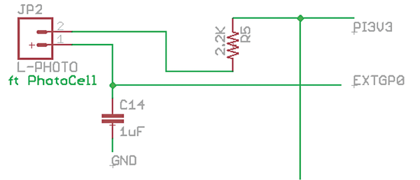 Figure 5: Simple AD converter on SunAir.
A photoresistor works as follows: When you shine light on it, the resistance drops. In the dark, the resistance is higher. If it is dark, it allows less current through than when it is light. To use this AD converter, you do the following sequence.
- Set the EXTGP0 signal (from a GPIO pin on the Raspberry Pi) to
0. Hold it for about 200ms. - Set the EXTGP0 to an input, making the GPIO pin a high impedance (open circuit) pin.
- Start timing.
- When the GPIO signal becomes a
1, take the time difference between step 3) and now.
That time difference is proportional to the time it takes C14 to charge from 0V to the 1 threshold of the Raspberry Pi GPIO input. The time is proportional to the resistance (hence the amount of light) the photoresistor currently has shining on it. In this way, this simple AD allows you to detect a set of graduated light changes.
Listing 1 shows the Arduino code for using this circuit. The Raspberry Pi code will be very similar.
Listing 1
Photoresistor Code
01 // Photoresistor code for SunAir
02
03 int getLightReading(int pinUnderTest)
04 {
05       // Start by setting GP to GND
06       pinMode(pinUnderTest, OUTPUT);
07       digitalWrite(pinUnderTest, 0);
08
09
10       // Hold 200ms
11       delay(200);
12
13       // Turn GP to HIGH Z (INPUT)
14       pinMode(pinUnderTest, INPUT);
15       int GPValue;
16       long microsStart;
17       long microsEnd;
18       microsStart = micros();
19       long i;
20       while(1)
21       {
22         // READ GP0 until it becomes 1
23         i = i+1;
24         GPValue = digitalRead(pinUnderTest);
25
26         microsEnd = micros();
27         if (GPValue == 1)
28           break;
29
30       }
31       return microsEnd - microsStart;
32 }
These two photoresistor ADs and the SunTracker tubes (3D printed) can pinpoint where the sun is and turn the panels to face the sun using a servomotor or stepper motor.
Other Modules
In my watchdog timer article [9], I discussed watchdog timers and how to use one to make a small computer system more reliable. The Watchdog Timer Enable circuitry on SunAir disables the watchdog timer if the supply voltage is too low (less than 4.65V in this case). This keeps the watchdog timer from trying to start up the computer when there isn't enough power to run the computer properly.
Hobby servomotors are an inexpensive method of motion control. They provide an off-the-shelf solution for most hobbyist's needs. Servomotors allow quite accurate positioning of motors via PWM control, which harkens back 30 years or more to pure analog systems. Interfacing a servomotor to SunAir is simple: Just connect a servo to JP15 on the SunAir board, GND, VDD5 (the SunAir power supply) and SIG. SIG is connected to a GPIO pin on the Arduino or Raspberry Pi and provides the control signal to the servomotor. For information on how to control a servomotor with your Raspberry Pi, check out the tutorial on Hertaville [14].
Interfacing a stepper motor to SunAir is a little more complicated (Figure 6). SunAir does not have a stepper motor driver so I decided to use the MouseAir motor controller board (Figure 7) [15] with an L293D dual H-bridge motor driver. Instructables has an excellent tutorial [16] and Seattle Robotics has a very usable tutorial for controlling a stepper motor using an L293D [17].
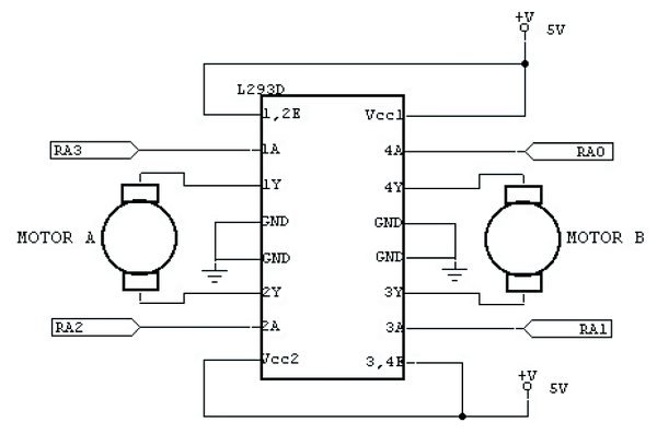 Figure 6: Block diagram of L293D connected to a stepper motor.
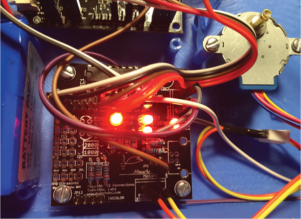 Figure 7: MouseAir motor controller board using an L293D.
The L293D can be used with servomotors, stepper motors, or DC motors, and SunAirPlus has a space on the board that allows users to plug in their own L293D. The VDD5 from the SunAir board powers the motor and the L293D IC on the MouseAir controller board [18]; then, I use GPIOs to control the various signal for the L293D IC. Several prebuilt boards for the L293D are available.
To make a stepper motor move forward a step, you need to activate, deactivate, and reverse the two motor coils in a specific pattern. Reversing the pattern makes the motor move back one step. Listing 2 is the code for an Arduino advancing a stepper motor one step. The code for reversing a step is just the inverse (Listing 3). The code is very similar for the Raspberry Pi.
Listing 2
Advance a Stepper Motor
01 void forwardStep()
02 {
03    float StepDelay = 50;
04
05   // step 1
06   digitalWrite(Motor1A, 1);  // coil 1a
07   digitalWrite(Motor3A, 1);  // coil 2a
08   digitalWrite(Motor2A, 0);  // coil 1b
09   digitalWrite(Motor4A, 0);  // coil 2b
10   delay(StepDelay);
11
12
13   // step 2
14   digitalWrite(Motor1A, 0);  // coil 1a
15   digitalWrite(Motor3A, 1);  // coil 2a
16   digitalWrite(Motor2A, 1);  // coil 1b
17   digitalWrite(Motor4A, 0);  // coil 2b
18   delay(StepDelay);
19
20
21
22   // step 3
23   digitalWrite(Motor1A, 0);  // coil 1a
24   digitalWrite(Motor3A, 0);  // coil 2a
25   digitalWrite(Motor2A, 1);  // coil 1b
26   digitalWrite(Motor4A, 1);  // coil 2b
27   delay(StepDelay);
28
29   // step 4
30   digitalWrite(Motor1A, 1);  // coil 1a
31   digitalWrite(Motor3A, 0);  // coil 2a
32   digitalWrite(Motor2A, 0);  // coil 1b
33   digitalWrite(Motor4A, 1);  // coil 2b
34   delay(StepDelay);
35
36 }
Listing 3
Reverse a Stepper Motor
01 void reverseStep()
02 {
03
04   float StepDelay = 50;
05   // step 4
06   digitalWrite(Motor1A, 1);  // coil 1a
07   digitalWrite(Motor3A, 0);  // coil 2a
08   digitalWrite(Motor2A, 0);  // coil 1b
09   digitalWrite(Motor4A, 1);  // coil 2b
10   delay(StepDelay);
11
12   // step 3
13   digitalWrite(Motor1A, 0);  // coil 1a
14   digitalWrite(Motor3A, 0);  // coil 2a
15   digitalWrite(Motor2A, 1);  // coil 1b
16   digitalWrite(Motor4A, 1);  // coil 2b
17   delay(StepDelay);
18
19   // step 2
20   digitalWrite(Motor1A, 0);  // coil 1a
21   digitalWrite(Motor3A, 1);  // coil 2a
22   digitalWrite(Motor2A, 1);  // coil 1b
23   digitalWrite(Motor4A, 0);  // coil 2b
24   delay(StepDelay);
25
26  // step 1
27   digitalWrite(Motor1A, 1);  // coil 1a
28   digitalWrite(Motor3A, 1);  // coil 2a
29   digitalWrite(Motor2A, 0);  // coil 1b
30   digitalWrite(Motor4A, 0);  // coil 2b
31   delay(StepDelay);
32 }
Buy this article as PDF
(incl. VAT)
Buy Raspberry Pi Geek
US / Canada
UK / Australia
Related content
-
Digital logic

We show how to use a logic analyzer to isolate problems in your hardware setup.
-
Digital logic

We show how to use a logic analyzer to isolate problems in your hardware setup.
-
SunRover Part 2 – Solar Power Controller/Power System

Putting power in your robot is more than just running wires – you'll need to make sure the power supply doesn't cause interference that will disrupt other components. This article explores the problem of electrical noise and describes the design for a multiplexing solar power system.
-
Getting more power from your solar panels

How much extra power can a solar panel collect by tracking the sun? SwitchDoc Labs puts it to the test.
-
Building the SunRover navigation system

The Switch Doc continues his effort to build a solar-powered robot. This month the emphasis is on the navigation system.
