The Raspberry Pi takes over a greenhouse
Power Supply
The various plugin modules created for a board measuring 80x100mm (3x4 inches) can all be placed on the backplane. As in the earlier version of the project, the sun supplies the power for this rebuilt automation project using the same charge regulator. The only difference is that the module is now located inside the electrical control housing.
The power supply module (Figure 3) comprises two prefabricated LM2596S step-down regulators (Table 2) [4]. The first module generates the 5V needed by the Raspberry Pi, and the second delivers the 3.3V needed by many of the components. The LEDs for the voltage indicator are not absolutely necessary; however, you should not do without the circuit breaker, because very high voltages can occur if the system shorts out. Before putting the voltage board on the backplane, you should adjust the output voltage for the modules with a multimeter in the 10A current scale while turning the brass knob on the blue potentiometer.
Table 2
LM2596S Specs
| Size | Value |
|---|---|
| Input voltage |
3.2-40V |
| Output voltage |
1.25-35V (adjustable) |
| Maximum output power |
<3A |
| Highest efficiency |
92% |
| Output ripple voltage |
<30mV |
| Frequency |
65KHz |
| Temperature range |
-45 to +85 degrees |
| Size |
43x21mm (~1.5x13/16 inch) |
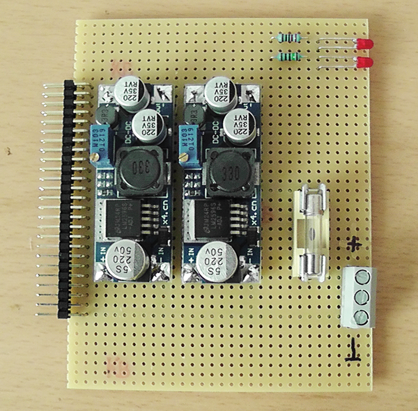 Figure 3: The power supply module. The circuit breaker prevents potential damage.
I/O, I2C, and Sensors
The CPU module consists of a first-generation Raspberry Pi mounted on a half Eurocard (Figure 4). The pins for I2C communication lead from the Rasp Pi to the bus. If CPU performance is not high enough, the module can easily be taken off and exchanged for an RPi2. A simple web front end serves as the control for the greenhouse. To avoid the need for additional cables, the greenhouse talks to the Raspberry Pi via a WiFi adapter in the local network. (See the box titled "Edimax EW-7711UAn.")
Edimax EW-7711UAn
Two versions of the Edimax EW-7711UAn WiFi adapter are currently available. Version 1 recognizes the Raspbian kernel without problem; however, version 2 comes with a new chip from the manufacturer that is not yet compatible with Raspbian [5], so the adapter won't work properly. Edimax offers source code for the corresponding kernel module [6], which can be compiled on the Raspberry Pi, but if you want to save yourself some time and trouble, you should probably purchase a WiFi adapter that comes with a driver in Raspbian.
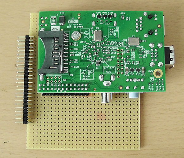 Figure 4: Even the Rasp Pi gets its own pluggable module.
The digital I/O module contains a PCF8574 from Texas Instruments [7]. The I/O expander for the I2C component has eight 8-bit digital input or output ports. Four of these come ready to assume control of the SRD-05VDC relay modules [8], which turn devices on and off. The remaining four serve as digital input ports. Optical couplers isolate the inputs galvanically, so any damages resulting from a malfunction are limited with respect to the other components.
All I2C devices are assigned a fixed 7-bit address by the manufacturer, but you can change it using DIP switches. By setting the I2C address for the PCF8574, you can operate several modules on the bus if necessary (Figure 5).
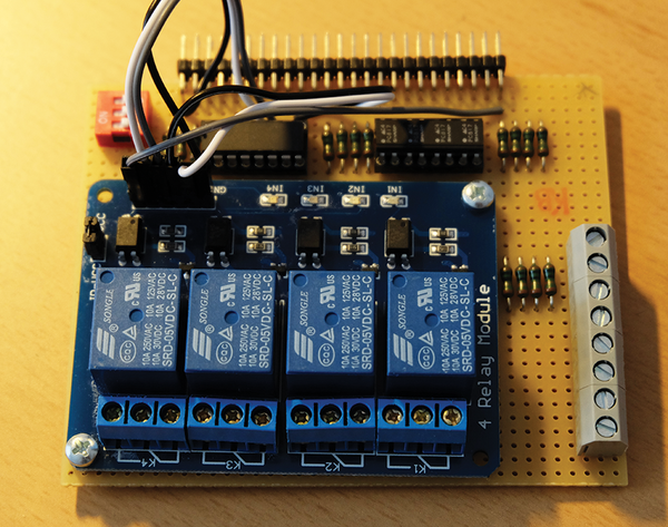 Figure 5: The digital I/O module simplifies the process of integrating additional sensors and actuators into the digital greenhouse project. The PCF8574 is at top left, to the right of the orange DIP switches.
The output driver of the PCF8574 comes with a peculiarity, in that it can have a current of up to 20mA to ground. The driver behaves this way because the PCF8574 possesses quasi-bidirectional I/O ports. Whereas a true bi-directional port has an output register with two states, 0 and 1, and a data direction register with two states, input and output. A quasi-bidirectional port, on the other hand, just inverts the signals for the greenhouse outputs; a pin set to output high, then, is used as an input.
The extender board extends the I2C bus for connecting external sensors to the outside. In the current construction, the communication with the two LM75 temperature sensors works error free despite wires 3m long (Figure 6). An additional I2C bus driver on the board will improve communication when longer distances are involved or when disturbances occur in transmission. However, the I2C bus is actually intended for communication inside of devices and not as a fieldbus.
 Figure 6: The bus extender with its 3m-long cable and the two LM75 temperature sensors.
« Previous 1 2 3 Next »
Buy this article as PDF
Pages: 6
(incl. VAT)
Buy Raspberry Pi Geek
US / Canada
UK / Australia
Related content
-
Building a Raspberry Pi greenhouse

A greenhouse environment has to be just right. The temperature can't climb too high or sink too low, and the plants need water. Why not put your Raspberry Pi to work as the gardener?
-
Android Pi

Your Android device can be a versatile companion for Raspberry Pi. We describe some useful apps to help you make this happen.
-
PHP on Raspberry Pi

Getting started with PHP on Raspberry Pi is easy. We show how to build a simple PHP app to control an LED.
-
An interactive Advent calendar

An Advent calendar during the Holiday season is a lovely tradition, but the calendars on the market are rather ordinary. We describe a Rasp Pi project that lets you create an innovative and unique Advent calendar.
-
Getting to know the Raspberry Pi I2C bus

When the Rasp Pi GPIO connection capabilities are insufficient for your project, you can turn to the industry-standard I2C data bus to communicate with actuators and sensors.
