A new way of no-solder prototyping
Digital Examples
One simple, yet visually interesting, Grove digital device is the fan module (Figure 8). I simply connected GPIO17 to D0 and the 5V and GND pins using jumper-to-Grove connector cables. (Always have these handy!) The software is very simple, as well (Listing 1). The only tricky part of the code is using the try … except block to make sure the GPIOs are turned off (actually floating) when the program exits; otherwise, a bug in your code could leave the fan running.
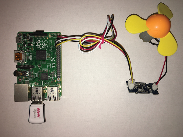 Figure 8: Grove Fan hooked up to the Raspberry Pi.
Listing 1
Grove Fan
01 #
02 # Test the Grove Fan
03 #
04 # Digital Grove Connector
05 #
06 # Gnd, 5V, GPIO4, GPIO17
07 # Grove
08 # Gnd VCC D1 D0
09 #
10
11 import time
12 import RPi.GPIO as GPIO
13 GPIO.setwarnings(False)
14
15 GPIO.setmode(GPIO.BCM)
16 GPIO.setup(17, GPIO.OUT)
17
18 try:
19     while (1):
20
21         GPIO.output(17, GPIO.HIGH)
22         time.sleep(2.0)
23         GPIO.output(17, GPIO.LOW)
24         time.sleep(2.0)
25
26
27 except KeyboardInterrupt:
28     # here you put any code you want to run before the program
29     # exits when you press Ctrl+C
30     print "Keyboard Interrupt"
31
32 except:
33
34     print "Other error"
35
36 finally:
37     GPIO.cleanup() # this ensures a clean exit
Another example of a digital Grove module is the Grove-EL driver for powering an EL (electroluminescent) wire (Figure 9). I wanted to use software PWM (pulse width modulation) to brighten and darken the EL (Listing 2) to illustrate a point about the Raspberry Pi. Because the Raspberry Pi runs a complex multitasking operating system (called Linux), the software timing for each of the pulses can be delayed by other important tasks happening inside the operating system. Therefore, you will see it flicker a bit, and differently each time. Using an Arduino or hardware PWM would produce a much smoother signal. When you are operating servomotors with software PWM, you will see the same kind of event, with a shaking – almost jittering – servomotor.
 Figure 9: Grove-EL driver hooked up to the Raspberry Pi.
Listing 2
Rasp Pi Software PWM
01 #
02 # Test the Grove EL Interface
03 # Digital Grove Connector
04 #
05 # Gnd, 5V, GPIO4, GPIO17
06 # Grove
07 # Gnd VCC A4 A5
08 #
09 import time
10 import RPi.GPIO as GPIO
11 GPIO.setwarnings(False)
12
13 GPIO.setmode(GPIO.BCM)
14 GPIO.setup(17, GPIO.OUT)
15
16 try:
17     while (1):
18
19
20         # now do PWM on the line
21         p = GPIO.PWM(17, 50)    # 50 Hz
22         p.start(0.0);
23         for dc in range(0, 101, 5):
24             p.ChangeDutyCycle(dc)
25             time.sleep(0.1)
26         for dc in range(100, -1, -5):
27             p.ChangeDutyCycle(dc)
28             time.sleep(0.1)
29         p.stop()
30
31 except KeyboardInterrupt:
32     # here you put any code you want to run before the program
33     # exits when you press Ctrl+C
34     print "Keyboard Interrupt"
35
36 except:
37
38     print "Other error"
39
40 finally:
41     GPIO.cleanup() # this ensures a clean exit
One thing to remember about both of the digital examples shown here is that they take a significant amount of current. Your Raspberry Pi might not be able to support 5V from the GPIO header, so you might want to put an external 5V power supply on this circuit. If you are having power issues, the Raspberry Pi will reset or the red power LED on the Pi will start blinking.
I2C Example
To test the new SwitchDoc Labs Grove I2C four-channel expander/extender, I hooked up four Grove I2C devices and one non-Grove I2C device to show all four buses working at the same time while connected to a Raspberry Pi. This new board not only has Grove connectors, it has status LEDs for all four buses and pin headers for non-Grove devices. It also allows me to mix 5V and 3.3V Grove devices on different I2C buses.
« Previous 1 2 3 4 Next »
Buy this article as PDF
Pages: 6
(incl. VAT)
Buy Raspberry Pi Geek
US / Canada
UK / Australia
Related content
-
IoT on Your Raspberry Pi

The SunIOT project attaches a Grove base unit with a light sensor to a Raspberry Pi to measure various components of the light spectrum.
-
Measuring air quality with the Raspberry Pi

Monitor your environment with a Raspberry Pi and an air quality sensor.
-
Sending your data through the air

Build a low-powered wireless system for your outdoor weather station using inexpensive hardware.
-
Getting more power from your solar panels

How much extra power can a solar panel collect by tracking the sun? SwitchDoc Labs puts it to the test.
-
The Pi Wire
Arduino’s “Invent Your Future” Contest; Fedora for Rasp Pi; New Raspberry Pi Kits for Windows IoT Core; micro:bit Education Foundation.
