Controlling your Pi with an infrared remote

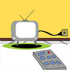
Lead Image © Anton Brand, 123RF.com

Remote Logic

A few tricks and some ready-made Linux tools will help you configure your Pi to respond to commands from the same kind of infrared remote control device you use with your TV.

MagPi

This article was writtenin partnership with The MagPi magazine: http://www.themagpi.com

The Raspberry Pi is often hailed for its incredibly cheap price. Other low-cost development and educational boards are available (e.g., the Beaglebone), but for some of these systems, the additional peripherals that are required can quickly amplify the cost. The Raspberry Pi, however, is designed from the ground up to use accessories that are already freely available in most households. For example, the choice of either HDMI or RCA video connectors allows you to use almost any TV made in the past 20 years as a display. The Pi is also (for the most part) plug-and-play compatible with your existing computer hardware – mice, keyboards, wireless dongles – and it uses a 5-volt micro-USB power supply, which is the standard for most phones and tablets (apart from those made by Apple). So, many people will already have a surplus of these accessories available in their household.

This article will allow you to unleash the power of yet another readily available household device – the infrared (IR) remote control. If you are anything like me, you have several of these in your home (Figure 1)! If you are not like me, then I have also covered using an IR receiver with a cheap, small, off-the-shelf IR remote.

Figure 1: Remotes in my house.

Short History of IR and Remote Control

The earliest example of a remote control using radio waves is described in the 1898 US Patent US613809 by the brilliant Serbian-American engineer Nikola Tesla. The first commercial remote intended to control a television or consumer device was the "Lazy Bones" remote, developed in 1950 by the Zenith Radio Corporation. It was a very different beast from the intricate designs found today – it only allowed you to turn the television on and off and to change channels and was actually directly connected to the television using a wire – a serious trip hazard!

Despite this hazard, the Lazy Bones proved to be a very popular device, and 5 years later, another engineer at Zenith (Eugene Polley) came up with the "Flashmatic," which was the first wireless TV remote. This control used directional visible light to turn the TV on and off and turn the channel dial clockwise or counter-clockwise. It had a few unfortunate disadvantages, though – you had to point the remote very precisely at the receiver, and on very sunny days you could be subject to random channel changes. Robert Adler, another Zenith Engineer, then created a remote control that communicated by means of ultrasonic sound – not audible by humans, but you risked annoying your dogs because it was audible by a lot of animals with good hearing. This was called the "Space Commander," and more than 9 million of these ultrasonic remotes sold in various iterations. Around the 1980s, companies such as BBC, ITT, and Viewstar Inc. started manufacturing remote controls using infrared light technology, which has continued to be the most common remote control technology for consumer devices in use today.

Infrared was first discovered in the year 1800 by an astronomer named William Herschel, who noticed that the heating effect from the sun on a thermometer was actually greater than that caused by the visible light spectrum. Herschel called these "Calorific Rays" – it wasn't until the late 19th century that the term infrared was coined, due to the wavelength of the infrared being larger than that of red in the visible spectrum.

Infrared communications first began to take hold in the 1980s in remote controls (as mentioned above) where basic functions were sent to a television or other consumer device using infrared. In the early 1990s, infrared data transfer (transferring files, pictures etc.) became a possibility, and in 1993, the Infrared Data Association was formed by about 50 companies to develop a series of protocols for wireless infrared data transfer. You might remember that phones, laptops, and PDAs around the late 1990s and early 2000s used to have infrared transmitters and receivers on them to transfer data wirelessly, before WiFi and Bluetooth were invented. (WiFi and Bluetooth are obviously superior because they do not need line-of-sight to transfer data.)

The IR Circuit

The basic IR receiver circuit for your Raspberry Pi requires only around US$ 5-10 worth of equipment (in addition to your Raspberry Pi, of course). A number of different sources for these components are shown in the box labeled "Parts List."

Parts List

  • Breadboard
  • Male to female jumper wires
  • 38kHz IR receiver (TSOP 4838 [1] or TSOP 38238 [2]
  • IR Remote (optional) [3] [4]

Depending on which IR receiver you choose, it will look something like Figure 2. Appearance can vary, but the pin layout is the same (1=OUT, 2=GND, 3=VS), and the functionality is very similar.

Figure 2: A typical IR receiver.

Setting up the IR configuration on a breadboard is easy – as the pin layout suggests, pin 1 is the signal output and therefore needs to go to a GPIO input pin (I have used GPIO18, which is the default pin used in the LIRC software, as you will see in the software setup section below). Pin 2 goes to ground, and pin 3 goes to Vs, which, in this case, is 3V3 (although the IR receivers are both rated for an input voltage of 2V5 to 5V5). The final layout is shown in the breadboard wiring diagram in Figure 3. Figure 4 shows a picture of my IR configuration in real life.

Figure 3: Breadboard wiring diagram for the IR configuration.
Figure 4: The real-life IR configuration.

It is, of course, possible to make this circuit with only three wires (by putting the ground and 3V3 straight to the main part of the breadboard), but it is good practice when using a breadboard to use the negative and positive power rails, because it makes things a lot easier and neater when dealing with larger circuits.

If you use an IR receiver that is different from the one shown in Figure 2, you should carefully read the datasheet to work out the pin layout. It could be completely different from the one I have just described. For a more permanent implementation, you could use a header connector, some proto-board, and the schematic shown in Figure 5.

Figure 5: Schematic diagram for the IR configuration.

Buy this article as PDF

Express-Checkout as PDF

Pages: 8

Price $2.95
(incl. VAT)

Buy Raspberry Pi Geek

SINGLE ISSUES
 
SUBSCRIPTIONS
 
TABLET & SMARTPHONE APPS
Get it on Google Play

US / Canada

Get it on Google Play

UK / Australia

Related content