Bring old toys back to life with Arduino
Back during the Christmas of 2004-2005, the Robosapien v1 by WowWee [1] was the cool toy to have: It walked, it talked, it did karate, and it cost less than 100 bucks. With 1.5 million units sold, you likely know somebody who has one of this cute robots.
Even if you don't have a Robosapien around, you can pick one up from eBay for as little as $20 [2] (I'm talking about the old v1; the new vX looks nearly the same but costs quite a bit more). Even if you're not interested in getting one of these cool toys, you will be able to apply what you learn here to other motor-driven projects. I chose the Robosapien because they're everywhere, and I had one in a closet. It walks, looks cool, and is relatively easy to hack with spectacular results.
Anatomy of Robosapien
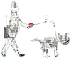
The Robosapien has one motor in each shoulder, one in each elbow (that twists the lower arm and makes the claws open and close), one at the waist, and one in each leg (Figure 1). Note that these are DC motors, not servos.
[...]
Buy this article as PDF
Pages: 8
(incl. VAT)
Buy Raspberry Pi Geek
US / Canada
UK / Australia
Related content
-
Bring old toys back to life with Arduino: Part II

Robotics are all the rage, and those old high-tech toys you might have lying around are ideal candidates for the Frankenstein/Arduino treatment.
-
Digital – Analog – Mechanical

As innovative companies consistently push the envelope of progress, antiquated hardware nearly two years old falls by the wayside. We take an old iPad, an Arduino Mega, and various other materials to create an in-dash climate control app.
-
Managing solar power systems with SunAir boards

A successful solar power project requires data analysis and the ability to modify the system to take advantage of prevailing weather conditions.
-
Control your littleBits projects with a homemade wireless remote
Make a custom handheld wireless remote control with littleBits Wireless Transmitter and Receiver bits and slider, knob, button, or toggle bits.
-
Infinite Possibilities
The open hardware movement continues to add, improve, and reinvent itself. No sooner did the Raspberry Pi Model B+ come on the scene, than the Raspberry Pi 2 debuted, adding a "1" to the name of all Rasp Pis that came before. Faster, smaller, and smarter devices appear almost daily, inspiring makers as they address ever more diverse real-world problems.
