HummingBoard Hack
The HummingBoard with its quad-core power, larger storage space, and faster interfaces is a strong competitor for the Raspberry Pi.
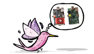
The Israeli manufacturer SolidRun has introduced the HummingBoard single-board computer (SBC), and the specifications are impressive. The HummingBoard ventures into performance levels that were previously closed to all but x86 processors. Compared with the Raspberry Pi, the HummingBoard has a much faster CPU, more storage, and a faster network interface. The HummingBoard also comes with throughput interfaces such as SATA and PCIe. Table 1 compares the HummingBoard with a Model B+ Raspberry Pi.
Table 1
HummingBoard vs. Raspberry Pi
| HummingBoard Professional i2EX | Raspberry Pi Model B+ |
---|---|---|
SoC |
Freescale i.MX6 Dual |
Broadcom BCM2835 |
ARM core |
Cortex A9 |
ARM1176JZF-S |
ARM instruction set architecture |
ARMv7 |
ARMv6 |
Clock rate core |
1,000MHz |
700 MHz |
Number of cores |
2 |
1 |
CPU benchmark |
2x to 10x Rasp Pi [12] |
Reference |
GPU |
Vivante GC2000 |
Broadcom VideoCore IV |
RAM |
1028MB |
512MB |
USB 2.0 ports |
2 |
4 |
Ethernet |
1Gbps1 |
100Mbps |
IR |
38kHz receiver |
38kHz receiver |
Video input |
15-pin MIPI CSI |
15-pin MIPI CSI |
Video output |
HDMI |
HDMI |
GPIO header |
26 pins2 |
40 pins |
PCIe |
Mini-PCIe connector |
– |
eSATA |
mSATA |
– |
Power consumption (max.) |
7.5W |
3.0W |
Price3 |
EUR 103/$100 |
EUR29/$35 |
Supplier |
||
1 Maximum possible bandwidth 470Mbps (SoC limitation) |
||
2 Form factor identical to Raspberry Pi Model B |
||
3 Additional shipping costs (Current: November 2014) |
As with the Rasp Pi, the HummingBoard family includes several models. However, the instruction set architecture for the HummingBoard is not limited to the ARMv6. The built-in Freescale i.MX6 system on chip (SoC) contains up to four ARM Cortex A9 processor cores that implement the ARMv7 instruction set architecture. The really big advantage is that armhf binary packets from Debian and its derivatives can be used directly. This is similarly true for other distributions. In light of these positives, the comparatively greater power consumption of the HummingBoard that occurs in many application sectors does not make a difference.
The HummingBoard does not yet offer a well-established community like the one that has arisen around the Raspberry Pi. The Raspberry Pi offers well-documented interfaces, numerous compatible peripheral devices, and a future-proof software ecosystem. In this article, I will address the extent to which the features of the HummingBoard family can compensate for its shortfalls in these areas.
The HummingBoard, which is more modular than the Raspberry Pi, consists of a micro system on module (SoM) that sits together with a cooling element on a carrier board (Figure 1). The MicroSOM consists largely of the i.MX6-SoC and the storage components. All together, there are four different MicroSoMs and four different carrier boards. As a result, the HummingBoard family has a total of eight members [1].
In addition to two carrier boards for the HummingBoard, SolidRun also manufactures devices for a small compact cover. These are the members of the CuBox-i product family. They have a reduced number of interfaces but have optics that can fit in with living room décor (Figure 2).
To figure out whether the behavior of the HummingBoard interface is compatible with that of the Rasp Pi, I will look at four simple applications. These include a serial console via UART, the control of LEDs via GPIO, serial peripheral interface communication and integration of the Rasp Pi camera module. In testing, the team used a Raspberry Pi Model B and a HummingBoard Professional i2EX as the test hardware. I put Raspbian on the test Rasp Pi and Debian "Jessie," which is the test version for Debian 8.0, on the HummingBoard in the form of images from SolidRun [2]. In both cases, installation was accomplished by simply copying to an SD and microSD card, respectively.
I activated the serial console with a PL2303HX USB to UART cable and minicom by connecting GND, 5V, RX, and TX crossed over with the GPIO headers. This approach worked on both SBCs without any problems. It is a good idea to make sure that the power supply for the HummingBoard is delivered via USB and that the 5V pin remains unconnected, because the PL2303HX cable itself cannot deliver enough power.
Figure 3 shows the setup for the control of an LED via GPIO [3]. I connected the pin board via a T-cobbler with the GPIO header of the Rasp Pi and likewise on the HummingBoard. After connecting an LED with a resistor in series on GPIO7 (pin 26), using the Rasp Pi as a control was easy. Listing 1 displays the process. The LED blinks synchronously with the output 0-1-0 … .
Listing 1
Using Rasp Pi as a Control
01 # mount -t debugfs none /sys/kernel/debug 02 # cat /sys/kernel/debug/gpio 03 GPIOs 0-53, bcm2708_gpio: 04 gpio-16 (led0 ) out hi 05 # echo "4" > /sys/class/gpio/export 06 # echo "out" > /sys/class/gpio/gpio4/direction 07 # cat /sys/kernel/debug/gpio 08 GPIOs 0-53, bcm2708_gpio: 09 gpio-4 (sysfs ) out lo 10 gpio-16 (led0 ) out hi 11 root@pi:/home/pi# val=1 12 # while : ; do 13 > echo $val > /sys/class/gpio/gpio4/value 14 > echo $val 15 > sleep 1 16 > val=$((1-$val)) 17 > done 18 0 19 1 20 0 21 1 22 [...]
Gert Leenders offers a good GPIO documentation for the HummingBoard in his blog [4]. Control using the HummingBoard (Listing 2) works very much the same as it does with the Rasp Pi with two exceptions. Pin 26 on the HummingBoard cannot be configured as GPIO at all. Therefore, it is necessary to use pin 22. Additionally, the numbering for the GPIOs is different. Pin 22 corresponds to GPIO 67 on the HummingBoard and GPIO 25 on the Raspberry Pi.
Listing 2
Using HummingBoard as a Control
01 # mount -t debugfs none /sys/kernel/debug 02 # cat /sys/kernel/debug/gpio 03 [...] 04 GPIOs 64-95, gpio-2: 05 gpio-67 (pin22 ) in hi 06 gpio-68 (PCIE RESET ) out hi 07 gpio-69 (gpio-ir-recv ) in hi 08 gpio-70 (pin15 ) in hi 09 [...] 10 # echo 67 > /sys/class/gpio/export 11 # echo out > /sys/class/gpio/gpio67/direction 12 # cat /sys/kernel/debug/gpio 13 [...] 14 GPIOs 64-95, gpio-2: 15 gpio-67 (pin22 ) out lo 16 gpio-68 (PCIE RESET ) out hi 17 gpio-69 (gpio-ir-recv ) in hi 18 gpio-70 (pin15 ) in hi 19 [...] 20 # val=1 21 # while : ; do 22 > echo $val > /sys/class/gpio/gpio67/value 23 > echo $val 24 > sleep 1 25 > val=$((1-$val)) 26 > done 27 1 28 0 29 1 30 0 31 [...]
The second test consists of activating the serial peripheral interface (SPI), developed by Motorola for a synchronous, serial data bus that connects digital switches according to the master-slave principle [5]. Numerous descriptions of how to do this on the Raspberry Pi are available [6] for reference to connecting memory, sensors, audio, display, or other peripherals to a SBC. The spidev_test.c
program comes together with the kernel source code and implements a loopback test, by which MOSI and MISO pins are connected to the GPIO header (Listing 3). However, this only works when spidev_test.c
is compatible with the kernel that is running on the Raspberry Pi.
Listing 3
Loopback Test on Raspberry Pi
01 $ gcc spidev_test.c -o spidev_test 02 $ ./spidev_test -s 100000 -D /dev/spidev0.0 03 spi mode: 0 04 bits per word: 8 05 max speed: 100000 Hz (100 KHz) 06 07 FF FF FF FF FF FF 08 40 00 00 00 00 95 09 FF FF FF FF FF FF 10 FF FF FF FF FF FF 11 FF FF FF FF FF FF 12 DE AD BE EF BA AD 13 F0 0D
Very little documentation exists on SPI communication with the HummingBoard. I loaded the spi_imx
kernel module in my test, but it did not create the desired device in /dev
, nor did it leave entries in the logfiles. The SPI devices appeared finally when I used an alternative Debian image [7] for the HummingBoard that was made by Igor Pecovnik. Even so, the devices appeared under a different name. Once the devices appeared though, the loopback test worked on the HummingBoard, too (Listing 4).
Listing 4
Loopback Test on HummingBoard
01 # gcc spidev_test.c -o spidev_test 02 # ./spidev_test -D /dev/spidev1.0 03 spi mode: 0 04 bits per word: 8 05 max speed: 500000 Hz (500 KHz) 06 07 FF FF FF FF FF FF 08 40 00 00 00 00 95 09 FF FF FF FF FF FF 10 FF FF FF FF FF FF 11 FF FF FF FF FF FF 12 DE AD BE EF BA AD 13 F0 0D
It is very easy to integrate the camera module on the Raspberry Pi and then activate it in Raspbian. All you have to do is configure it with raspi-config
and then, after a reboot, start taking photographs with
raspistill -o image.jpg
I looked online for instructions on how to activate the camera on the HummingBoard but couldn't find any. Other types of cameras appear to work, but I unable to test any of these because of a lack of hardware.
Pages: 6
Price $15.99
(incl. VAT)