Adding analog input to the Pi using the Digispark
Seen and Not Seen
The Digispark has six digital input/output pins numbered 0 to 5 along its top edge (from left to right with the USB connector pointed away from you). Four of those pins can also act as analog input ports, and the best pin to use is P2/A1. Table 1 shows the correspondence between digital and analog pins.
Tabelle 1
Digispark Digital/Analog Pins
| Digital | Analog |
|---|---|
| P0 |
– |
| P1 |
– |
| P2 |
A1 |
| P3 |
A3 |
| P4 |
A2 |
| P5 |
A0 |
A simple example that uses a Digispark (as opposed to a Digispark plus a Raspberry Pi) and a few of the components you'll need in the final project illustrates how the analog input works, which is what you'll be interested in later. The first bit you'll need is a potentiometer, which you'll use to regulate the blinking speed of an LED. A potentiometer (Figure 3) is a variable resistor, meaning you can regulate the voltage it outputs with a movable part, usually a knob or slide.
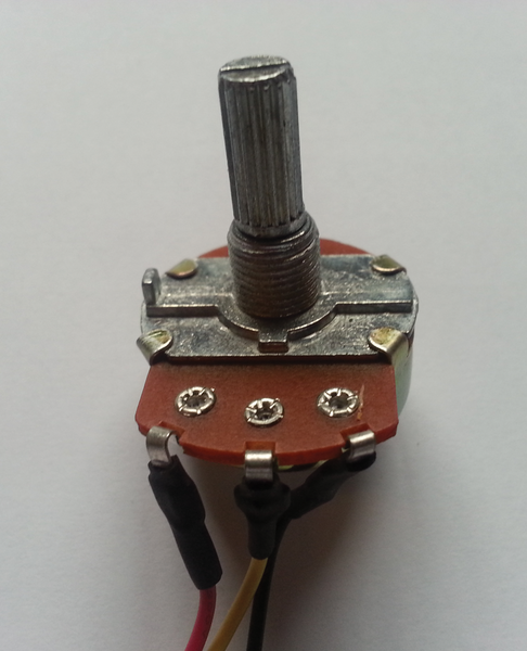 Figure 3: A typical potentiometer. The red wire feeds in the current, the black goes to ground, closing the circuit, and the yellow outputs the modulated current.
The most interesting wire in Figure 3 is the yellow one in the center, which outputs the modulated voltage that changes when you twist the knob, and it is what you want to measure on your analog pin. The illustration in Figure 4 shows you how to hook the potentiometer to the Digispark. The red wire is connected to the 5V output the Digispark supplies, the black wire is connected to Digispark's ground, and the yellow wire is connected to P2/A1. An LED is connected to P0.
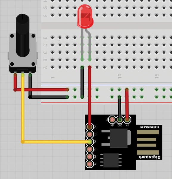 Figure 4: A Fritzing [5] circuit diagram of the Digispark, potentiometer, and red LED.
Once you've hooked everything up as shown in the diagram, open the Digispark Arduino IDE and enter the "sketch" (Arduino code) you see in Listing 2. Upload it to the Digispark by clicking on the Upload icon in the toolbar. When you see the message saying the sketch has been uploaded successfully, wait a few seconds until the LED starts blinking, then twiddle the dial on the potentiometer.
Listing 2
Variable Blinking
01 int sensorValue=0;
02
03 void setup()
04 {
05   pinMode(0, OUTPUT);
06 }
07
08 void loop()
09 {
10  sensorValue = analogRead(1); // Which corresponds to P2
11
12  digitalWrite(0, HIGH);
13  delay(sensorValue);
14  digitalWrite(0, LOW);
15  delay(sensorValue);
16 }
The farther counterclockwise you turn it, the slower the LED blinks. If you turn the knob clockwise, the LED blinks faster. That's because you are using the variable sensorValue to set the delay (lines 13 and 15), and in line 10 you are reading sensorValue off analog pin 1 (digital pin 2), the pin to which the potentiometer is connected. The values supplied by analog pin 1 vary between 0 and 1023, and the delay is measured in milliseconds. When you turn the knob all the way clockwise, you will experience virtually no delay, but when you turn it all the way counterclockwise, the delay is slightly longer than a second.
Dream Operator
To move on to the "safe" project, you need the Digispark to interact with the Raspberry Pi. To do that, you need to include a special library in your Digispark sketch called DigiUSB.h (Listing 3, line 1). This library is included by default with the Digispark setup, so if you have followed the installation described above, it should just work.
Listing 3
Potentiometer.ino
01 #include <DigiUSB.h>
02
03 int sensorValue=0;
04 int oldSensorValue=0;
05
06 void setup()
07 {
08   DigiUSB.begin();
09 }
10
11 void loop()
12 {
13  sensorValue = analogRead(1);
14  sensorValue = map(sensorValue, 0, 1023, 0, 9);
15
16  if (sensorValue != oldSensorValue)
17  {
18    DigiUSB.println(sensorValue);
19  }
20
21  oldSensorValue = sensorValue;
22  DigiUSB.delay(10);
23 }
Line 8 initializes communication over USB. This is when the Digispark will show up as an input/output device by reporting its bus and device ID. As before, you read in the value from the potentiometer, again connected to analog pin 1 (line 13), and then make it more manageable by mapping its value from 0 to 9 (line 14).
With map(), the original value of sensorValue (i.e., a number between 0 and 1023) is transposed to a scale that goes from 0 to 9. If sensorValue equals 0 on line 13, it will equal 0 on line 14. If it equals 1023 on line 13, it will equal 9 on line 14. If it equals anything in between on line 13, it will be adjusted proportionately to a number between 0 and 9 on line 14.
Because you don't want to send a constant stream over the USB channel, line 16 checks whether the value has changed since the last time you looked. If it has, line 18 prints it to the USB. The current sensor value becomes the old sensor value (line 21) and waits for a 100th of a second before going again. If you don't include the pause, you are guaranteed to confuse your USB system on the receiving end (i.e., on the Pi), and you will lose your connection with the Digispark.
Now, you can move your other computer over to your Pi, because the next step is to get the Pi to read the values the Digispark is sending over the USB and use them to build up a combination of numbers (e.g., several numbers from 0 to 9), compare it to a combination stored in the Pi's program, and then switch on one LED or another (Listing 4).
Listing 4
Combination.py
01 import sys, time
02 import RPi.GPIO as GPIO
03 from datetime import datetime, timedelta
04
05 # Digispark specific
06 import usb # 1.0, *NOT* 0.4: use *pip install pyusb* to install
07 from arduino.usbdevice import ArduinoUsbDevice
08
09 combo = []
10 master_Combo = []
11 red_LED = 24
12 green_LED = 25
13
14 GPIO.cleanup()
15 GPIO.setmode(GPIO.BCM)
16 GPIO.setup(red_LED, GPIO.OUT)
17 GPIO.setup(green_LED, GPIO.OUT)
18
19 def readCombo():
20
21     v_combo = []
22     fb_store='0'
23
24     while True:
25         try:
26             theDevice = ArduinoUsbDevice(idVendor=0x16c0, idProduct=0x05df)
27
28         except:
29             print "Dial not found! Attach your Digispark (with a dial) and rerun."
30             GPIO.cleanup()
31             sys.exit(0)
32
33         try:
34             feedback=""
35             while True:
36                 lastChar=chr(theDevice.read())
37                 if lastChar=="\n": break
38                 feedback=feedback+lastChar
39
40             print(feedback) # Comment this line in production
41             fb_store=feedback[0]
42
43             start_time=datetime.now()
44
45         except:
46             # Check if time on number is greater than 5 seconds
47
48             try:
49                 elapsed_time=datetime.now()-start_time
50                 if elapsed_time.seconds > 5:
51                     v_combo.append(fb_store)
52                     blinkLED(green_LED, 2, 0.2)
53                     start_time=datetime.now()
54
55                 if len(v_combo)==len(master_Combo): break
56
57             except:
58                 time.sleep(0.1)
59
60     return v_combo
61
62 def blinkLED(v_LED, times, speed):
63
64     GPIO.output(v_LED, GPIO.LOW)
65     for i in range(times):
66         GPIO.output(v_LED, GPIO.HIGH)
67         time.sleep(speed)
68         GPIO.output(v_LED, GPIO.LOW)
69         time.sleep(speed)
70
71 if __name__ == "__main__":
72
73     if len(sys.argv)==1:
74         print "Please input code combination."
75
76     else:
77
78         # Read combo from command line
79         master_Combo=sys.argv[1:]
80
81         while True:
82             combo=readCombo()
83             if combo==master_Combo:
84                 blinkLED(green_LED, 3, 0.3)
85                 break
86
87             else:
88                 blinkLED(red_LED, 3, 0.3)
89
90     GPIO.cleanup()
To begin, you need to do some housework by importing the modules you'll need later (lines 1 to 3). The most interesting module is RPi.GPIO, a module preinstalled in Raspbian that supplies code to read from and write to the Raspberry Pi GPIO pins. Line 6 brings in the Python USB module. This module is not usually installed by default, so you'll have to install it by hand; however, DO NOT use apt-get. In most Linux repositories, including those that Raspbian uses, the version of PyUSB available is the old 0.4 version. This will not work with your program; you're going to need the new 1.0 version.
Next, you need to install pip, the Python package manager, then you can install PyUSB using pip:
$ sudo apt-get install python-pip
$ sudo pip install pyusb
These commands grab and download the latest version of PyUSB from the main Python repositories. Line 7 brings in a Digispark-specific module. Again, this will not be installed on your system by default, so you'll have to install it manually. To get the module, clone the DigisparkExamplePrograms directory from the Digispark GitHub account into your directory:
$ git clone https://github.com/digistump/DigisparkExamplePrograms.git
and copy, move, or link the DigisparkExamplePrograms/Python/DigiBlink/source/arduino/ subdirectory to the directory from which you want to run your own program (your working directory). For example, if you cloned DigisparkExamplePrograms/ … into your working directory, cd into it and enter
$ ln -s DigisparkExamplePrograms/Python/DigiBlink/source/arduino
which creates a link to the arduino directory containing the module within your working directory.
From lines 9 to 17, the program continues with the housework, setting variables and making sure the GPIOs are ready to be used. You'll be hooking the red LED up to pin 24 (line 11) and the green LED to pin 25 (line 12). Note that you'll have to run this program as superuser (with sudo) because regular users don't have access to the Pi's GPIO interface.
Down in the main section (lines 71 on), you read in the master combination as arguments to the program entered on the command line. Clip off the first element of sys.argv in line 73; it's the name of the program (see the "sys.argv" sidebar). If you want the master_Combo to contain, say, ['1', '2', '3', '4'], you'd call the program like so:
$ sudo python combination.py 1 2 3 4
Although the combination may contain as many numbers as you like, they must all fall between 0 and 9, as was established in Potentiometer.ino (Listing 3).
sys.argv
Elements of a command entered at the command line are kept in a list (array) called sys.argv. The first item of the list is the program invoked at the command line. The next items in the list are any arguments entered after the program name. Because array numbering starts at zero, the elements of the sys.argv array are numbered [0], [1], [2], and so on. If you want the arguments to the command, you take from element [1] until the end of the array, as in Listing 4, line 79.
Next, an infinite loop (line 81) reads in the user's combination (combo) using the readCombo() function (I'll discuss this function in detail in a minute) and compares both the user's combo and the master_Combo defined when the program was run. If they are the same, the program blinks the green LED three times (line 84) using the blinkLED() function (lines 62-69) and exits the loop, ending the program. If the combination is not correct (line 87) the program flashes the red LED and goes through the loop again.
The blinkLED function takes three parameters: the LED to flash, the number of times it is flashed, and the speed at which it is flashed, Much more interesting is readCombo function (lines 19-60). This function reads in the combination from the potentiometer attached to the Digispark. When it's first called, it ignores the state of the potentiometer until the dial is twiddled. When the user finally turns the dial, it starts reading the input and waits until the user chooses a number. If the user stays on a certain number more than five seconds, the program assumes that is number selected as part of the combination and appends it to v_combo.
The program indicates a number has been accepted as part of the combination by blinking the green LED twice. The function runs through this routine as many times as there are numbers in master_Combo. When done, the routine exits the loop and returns control to the main function, where the combination entered by the user (combo) is compared with the combination entered by the operator (main_Combo), as already discussed.
Buy this article as PDF
Pages: 8
(incl. VAT)
Buy Raspberry Pi Geek
US / Canada
UK / Australia
Related content
-
Get your Pi to read analog data

The Raspberry Pi still lacks analog GPIOs that would allow it to read directly from temperature and light sensors, or even humble potentiometers. With an inexpensive chip and some software-fu you can grant the Pi the gift of analog sensing.
-
A home intrusion detection setup (sort of)

At least part of the popularity of the Raspberry Pi can be attributed to its high maker value; that is, a skilled maker with a Pi can build marvelous and beautiful things. Me? Not so much, but I was willing to try to build a home security system with the stuff in my junk box. Here's what happened …
-
A new way of no-solder prototyping

The Grove system's standardized connector and multitude of devices allow quick and easy project prototyping with your favorite small-board computers.
-
Write your own drivers for Arduino

So, you have some new kit for your Arduino – maybe some sensors or ICs – but programming them is clumsy and painful. Don't despair: You can make your life easier by writing your own drivers!
-
Use an analog sensor as a video game controller

We put our Analog-to-Digital converter to work reading positions from an analog sensor (a potentiometer) and control a bat in a simple implementation of the classic Breakout game.
