Automate and monitor the physical systems in your home
Building the System
In this example, we built a system one block at a time, where the blocks correspond to blocks in the block diagrams: we would build a block, test it, save it, and move on to the next block. By the time we had built all the blocks, we had about 60 files for the three Pis and four Arduinos.
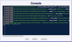
Each time we built a block, we'd edit and save our work from the Console page. The Console page keeps a record of every script run and every wire drawn. Each time we ran a script or created a wire, the corresponding script command displayed in the console. So, for example, after creating the devices and wires of this article, the Console looked like Figure 11. Although some of the lines are too long to fit within the Console window, you can see that an Arduino, a programmable device, a state machine device, and a wire were created. After each command is a [true, …] line, which is the result from the previously executed command. All the results show [true, …], because they executed successfully; bad commands would return [false, …].
If you copy all the lines from the Console and delete the result output from the ends of the lines, you end up with a script that recreates your work. In this way, we were able to save our work. Sometimes, when scripts looked too busy, we added additional blank lines, spaces, and comments (any text following a # is a comment). These elements made the scripts easier to read and didn't affect execution because the script interpreter ignores blank lines, extra spaces, and comments.
Once we had finished creating block-level scripts, we created top-level scripts. Top-level scripts assemble all the blocks together: For three Pis, that's three top-level scripts. Using the block diagrams as guides, we ran all the block-level scripts for each Pi, added the wires to connect the blocks, then tested the wiring. When we were satisfied, we copied the Console into the appropriate top-level script, made the final edits, and saved the lot.
Installation
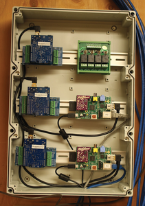
Each enclosure went on a wall panel (Figure 12): The Pi1 and Pi2 enclosure went into the utility room with many of the pre-existing systems, and the Pi3 enclosure went to the other end of the house near the furnace and water heater. After plugging in the Pis and giving each an Ethernet connection, the Pis were running, the Arduinos were running, and all three Virtual Wiring systems were running. Next, we wired in the various relays and sensors – about 50 signal wires. By design, all of the signals were low voltage and low current, so we used standard twisted pair wiring (Ethernet cables).
All the sense wires electrically looked the same: two wires that were either shorted together or open. For each sense pair, then, we connected one wire to an Arduino pin and an external pull-up resistor (Arduinos have built in pull-ups, but they were too weak to be reliable for this application) and grounded the other wire. When the wires were open, the Arduino saw an "on" voltage. When the wires were shorted, the Arduino saw an "off" voltage. To add the external pull-ups, we soldered resistors to Arduino Proto Shields and sandwiched a Shield between each Arduino and Aussie Shield. The Aussie Shields made wiring pretty simple, because they have a push-button terminal for each Arduino signal; therefore, signal wires could be added or removed just by pushing a button.
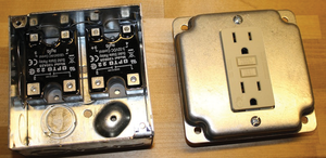
The relay signals also came in pairs. One of the pair was grounded, and the other was connected to an Arduino output pin. Most of the relays were solid state, and these fit neatly into standard electrical boxes (Figure 13). Note: If you are not an electrician, you must have an electrician install your high-voltage relays; high voltages are dangerous.
Buy this article as PDF
(incl. VAT)


