Building a Raspberry Pi greenhouse
Controlling the Greenhouse
To avoid damage to the Raspberry Pi that might otherwise be caused by the greenhouse environment, I packed the computer and the electronic charging system into a waterproof housing. The handful of electronic components can be soldered onto an off-the-shelf circuit board. The circuit layout, which you can download from the Raspberry Pi Geek FTP site [1], provides an overview of how everything fits together.
Because the GPIO interface 3.3V is insufficient to start the switching action of the MOSFETS, I build a small preliminary stage via a photocoupler. This approach also saves the life of the Rasp Pi in the case of a surge in the power amplifier. The MOSFETS get mounted on cooling elements because they become very hot running in PWM mode. Running in pure switching mode would not require cooling.
To make the assembly easier in the greenhouse, I placed all connections on a terminal strip. As described in the box titled "Making 5 Out of 12," a DC to DC converter assumes the role of voltage supply. Figure 2 shows how the intelligent greenhouse control looks when assembly is finished and it is mounted in a waterproof housing.
Making 5 Out of 12
To get the 5V needed by the Raspberry Pi out of the 12V from the solar energy electrical system, I use a DC to DC converter TSR 1-2450 from the Traco Power company [2]. The converter works better than a linear voltage regulator because it has significantly less power loss. In this case, a linear regulator would convert more power into heat than the power the Rasp Pi needs to operate. The TSR 1-2450 achieves an efficiency factor of more than 90 percent in this project and produces almost no heat. With respect to voltage supply, it is possible to supply voltage to the Raspberry Pi over pin 2 (+5V) and pin 6 (0V) on the GPIO interface, so there is no need for a USB cable.
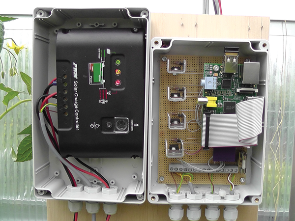 Figure 2: The greenhouse control board when completely assembled.
Don't place artificial limits on yourself when you implement your own system; however, you should remember the mundane and yet very necessary items like an on-off switch. The Raspberry Pi itself doesn't have one, and it's connected directly to the power supply. Figure 3 shows the pinouts of all the semiconductors that were used.
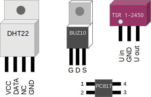 Figure 3: Knowledge of the pinouts is helpful when populating the circuit board.
The circuit layout in greenhouse_2.sch shows the disposition of the DHT22 [3] humidity and temperature probes, the ordinary PC fans used for ventilation, and a 12V submerged pump (available in home building supply stores) for watering the plants. A laboratory power supply replaces the battery and the solar panel during test mode.
Software
An updated version of Raspbian on an SD memory card serves as the basis for the software. The card should have a minimum 8GB capacity for applications and data to plan for the long term. After installing the system, you should download several updates and install an Apache web server, a MySQL database, and the tools needed to compile the programs (Listing 1). When installing the database server, you will be asked to set a MySQL root password; remember it, because you need this password later.
Listing 1
Update and Install Software
$ sudo apt-get update && sudo apt-get dist-upgrade
$ sudo apt-get install apache2 mysql-server php5-mysql build-essential git-core
After installing the component parts of the server, you'll need the WiringPi library [4], which allows you to read the GPIO interface with a simple command:
$ git clone git://git.drogon.net/wiringPi
$ cd wiringPi
$ ./build
Compiling the program takes a while because the Rasp Pi does not exactly run like lightning. Once the build is finished, you should perform the first test and read the data from the GPIO ports with gpio readall (Listing 2).
Listing 2
Reading the GPIO Ports
$ gpio readall
+----------+-Rev2-+------+--------+------+-------+
| wiringPi | GPIO | Phys | Name   | Mode | Value |
+----------+------+------+--------+------+-------+
|      0   |  17  |  11  | GPIO 0 | IN   | Low   |
|      1   |  18  |  12  | GPIO 1 | IN   | Low   |
|                      [...]                     |
|     19   |  30  |   5  | GPIO10 | ALT2 | Low   |
|     20   |  31  |   6  | GPIO11 | ALT2 | Low   |
+----------+------+------+--------+------+-------+
Now the DHT22 temperature and humidity sensors need a driver, which is available from the developer's GitHub page [5]; build it according to Listing 3. This build process will also take some time. Once it is completed, you should read the two DHT22 sensors with loldht (you need root privileges):
Listing 3
DHT22 Drivers
$ git clone https://github.com/technion/lol_dht22
$ cd lol_dht22
$ ./configure
$ sudo make install
$ sudo loldht 8
$ sudo loldht 9
At this point, you can define sensor 8 for the interior of the greenhouse and sensor 9 for the exterior. I use the PWM output of the Rasp Pi for controlling the fans. Although these are not so easy to configure, you should not let this stand in the way of making an attempt. Pin 12 is intended for the PWM operation:
$ gpio mode 1 pwm
$ gpio pwm-bal
$ gpio pwmr 100000
$ gpio pwm 1 14000
For the fans used in this project, the values range between 14,000 and 17,000. The values vary from fan to fan; therefore, it is best to determine the upper and lower limits for each of the fans in use. You will need to enter these values in later scripts.
« Previous 1 2 3 4 Next »
Buy this article as PDF
Pages: 6
(incl. VAT)
Buy Raspberry Pi Geek
US / Canada
UK / Australia
Related content
-
The Raspberry Pi takes over a greenhouse

Keeping up with a garden is a lot of work. Luckily, with a Raspberry Pi, you can automate your greenhouse.
-
SunRover part 1: Track motor controller/power system

Take your first steps in building a solar-powered robot.
-
Capture temperature data with the ESP8266 and the LM75 Sensor

We use the ESP8266 chip which gathers temperature data from a sensor and then forwards it via REST to a Raspberry Pi, where it's stored in a database.
-
SunRover Part 2 – Solar Power Controller/Power System

Putting power in your robot is more than just running wires – you'll need to make sure the power supply doesn't cause interference that will disrupt other components. This article explores the problem of electrical noise and describes the design for a multiplexing solar power system.
-
Protect your electronics from lightning strikes

Add a lightning detector to your vulnerable projects via the I2C bus to protect them from electrical storms.
