Using the Hover

Lead Image © Brankica Vlaskovic, 123RF.com

Flying High

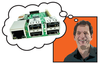
The Hover board is an intriguing piece of hardware that will make interacting with your Raspberry Pi much more interesting.

This little square of awesome only measures about 6 square centimeters (just over 2 square inches), but it has great potential for exciting and fun projects. The Hover board [1] has five sensitive tap areas: center (in Figure 1, the central, gridded area), north (the narrow band at the top of the board), south (the band at the bottom), east (the band on the right), and west (the band on the left). It can also detect double taps (similar to double clicks on a mouse button) and simultaneous taps on multiple areas. You could, for example, tap on north and east at the same time, and the Hover would pick it up just fine.

Figure 1: The Hover packs five tapping areas and detects four kinds of "hovering" swipes in a 6cm square.

What makes the Hover really exciting is that it can also detect movements you make above it, without touching it. It can detect four kinds of "hovering" swipes (or gestures in Hover parlance): up, down, left, and right. To execute an up swipe, for example, you'd wave your hand over it from bottom to top, for a down swipe from top to bottom, and so on.

This all works because the board sends a stream of 8 bits over its SDA/SCL pins when an event is detected. The first 3 bits indicate the type of event – a tap or a swipe. The other 5 bits are directional, indicating where the tap was detected or the direction of the swipe. You can see how this works in Figure  2.

If the first three bits are 010, then the board has been tapped; as shown in Figure 2, the tap is on the north area. If the first three bits are 001, however, then the board has detected a hovering gesture. In Figure 2, the swipe is a bottom to top (i.e., an up) swipe. See the box called "The Physics of Hovering" for more information.

The Physics of Hovering

How does the Hover really work, though? Well, the technology is similar to that of capacitive tablet screens: The screen itself generates an electric field. When you touch a conductive element (like your bare finger) to the screen, the transfer of charge to your body creates a distortion in the electrical field. The tablet picks up the coordinates of the distortion and triggers an event at that position.

In the case of the Hover, if you turn it over, you'll see a tight grid of capacitive electrodes. These electrodes create an electrical field that reaches up, above the board, to a height of approximately 12 centimeters (about 5 inches). When you move an electrically conductive body (e.g., your hand) into the field, again the field is distorted as electricity is transferred to your hand, and the electrodes pick up the distortion. Although the resolution of the field is too coarse to detect the exact coordinates of the distortion, by detecting which electrodes register the distortion over time, the Hover can work out which way the body is moving within the field and inform of the direction of the swipe.

Note that the body that enters the electric field has to be conductive. That's why capacitive touchscreens don't work while you're wearing gloves, and the Hover won't register anything if you wave a plastic ruler around over it, for example.

Yes, I tried both. For science.

Figure 2: Hover sends eight bits over the wire to your Pi or Arduino when it detects an event.

Wiring Up

To connect your Hover to your Raspberry Pi, you need to wire it as shown in Figures 3 and 4. Just in case that's not clear, here is a detailed explanation of what plugs in where:

Figure 3: How to connect the Hover to your Raspberry Pi.
Figure 4: Top: the Hover connected to the Raspberry Pi. Bottom left: detail of the connections on the Hover's end. Bottom right: detail of the connections on the Pi's end.
  • 1. The Hover is powered by any of the two 3V3 pins on the Pi, so you connect one of those to the 3V3 pin on the Hover (red cable) and hook the Hover's 3V3 pin to its own HOST_V+ pin (white cable on the breadboard).
  • 2. The Hover sends information over its SCL (clock) and SDA (data) pins, so you connect those (yellow and orange cables, respectively), and you hook them up to the Pi's GPIO 3 (the Pi's SCL input pin) and GPIO 2 (the Pi's SDA input pin).
  • 3. Connect the Hover's GND pin to any of the Pi's GND pins (black cable).
  • 4. Connect the Hover's RESET and TS pins to any of the Pi's remaining general purpose GPIOs. The official documentation [2] recommends GPIOs 23 and 24, because, it says, that's what's hardcoded into the Hover Python module. It seems, however, that the module was modified after the documentation was written, and you can now pass the GPIOs of your choice to the module as parameters. I decided not to risk it and hooked up the TS pin to GPIO 23 (blue cable) and the RESET pin to GPIO 24 (green cable), as they say on the Hover website.

If you wired everything correctly, the red LED on the Hover should come on when you power up the Pi. If it doesn't, review each connection, making sure you plugged each cable into its corresponding GPIO.

Testing

Now that you have the Hover all wired up, I'll show how to get it talking to your Pi. You're going to need a set of drivers and tools to make this happen:

$ sudo apt-get install i2c-tools

The I2C tools and the drivers that come with them are very useful because the I2C protocol regulates input from devices, like the Hover, that use the SDA and SCL pins. If you often tinker with hardware, you'll need these for future projects.

You should also install the Python bindings for Linux SMBus access through i2c-dev:

$ sudo apt-get install python-smbus

These will come in useful later when you want to use Python with the Hover.

Now you need to load the I2C modules into your kernel. You can do this by typing:

$ sudo modprobe i2c-dev
$ sudo modprobe i2c-bcm2708

You could load the modules manually like this every time you needed to use the Hover, but you're probably better off if you have Raspbian load them automatically at boot time by adding them to the /etc/modules file. To do this, use your favorite editor (I use Vim) to open the file,

$ sudo vim /etc/modules

and add the following lines to the bottom of the file:

i2c-dev
i2c-bcm2708

Save and close the file.

Now you have just one more thing to do: For some reason, the i2c-bcm2708 module is blacklisted in the default Raspbian setup. This means the driver will be blocked when you try to load it, unless you take it off the blacklist. To do so, open the /etc/modprobe.d/raspi-blacklist.conf file with your text editor

$ sudo vim /etc/modprobe.d/raspi-blacklist.conf

and comment out the line that says

blacklist i2c-bcm2708

by adding a hash in front of the line:

# blacklist i2c-bcm2708

Reboot your Pi and run the diagnostic program:

$ sudo i2cdetect -y 1

You should see something like the output shown in Figure 5. The 42 somewhere within the grid is the Hover identifying itself to the Pi.

Figure 5: The 42 in the middle of the grid is the Hover identifying itself to your Raspberry Pi.

Buy this article as PDF

Express-Checkout as PDF

Pages: 8

Price $2.95
(incl. VAT)

Buy Raspberry Pi Geek

SINGLE ISSUES
 
SUBSCRIPTIONS
 
TABLET & SMARTPHONE APPS
Get it on Google Play

US / Canada

Get it on Google Play

UK / Australia

Related content

  • Innovations

    I'm amazed at the energy and inventiveness of the Raspberry Pi Foundation. Almost every time we print one of these magazines, we have something new to talk about. This time we're featuring the new Raspberry Pi B+ model. The B+ adds power and convenience to the beloved Rasp Pi B.

  • Raspberry Pi IR remote

    Turn a Raspberry Pi into an IR remote control for your DSLR, TV, or any other device with an IR port.

  • Build a complete game with Python and PyGame

    We show how to use PyGame to implement a fully playable version of the classic "robots" game.

  • Add some security to your projects

    Blank RFID (Radio Frequency ID) cards along with a USB-based RFID card reader can offer an easy and low cost solution for your Pi security projects.

  • SIMPL is as SIMPL does

    The low-priced, small-footprint Rasp Pi and the open source, compact SIMPL messaging toolkit are a natural fit for application developers.