Two LED projects for light and sound
Lighting the Lightning
The electronics side of this project is about as simple as it gets. A TIP31 transistor rated at 3 amps and a current-limiting resistor are the entire circuit. The transistor base is driven by the Raspberry Pi's GPIO pin, and the LEDs are connected to the transistor's collector. When the GPIO pin goes HIGH, the LEDs light. That circuit is on the board twice, one for each lightning panel. A commercial beam-break sensor also connects here to set off the storm as people approach that area of the layout. A 12-volt power supply brings it all together. Figure 5 shows the board being tested on the bench.
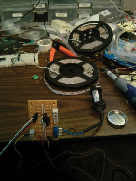 Figure 5: The main driver board for the lightning is in the lower left of the picture. The two transistors are on the top of the board, and the four-position terminal block on the right is where the panels connect. The beam-break sensor is connected to the blue terminal block. The four-pin cable connects to the Raspberry Pi; the LED strips are in the background.
To build the lightning panels themselves, I cut two pieces of 12x6-inch masonite (Figure 6). I cut LED strips into foot-long sections and used the built-in tape to attach them to the masonite. The most tedious part was soldering wires between each strip.
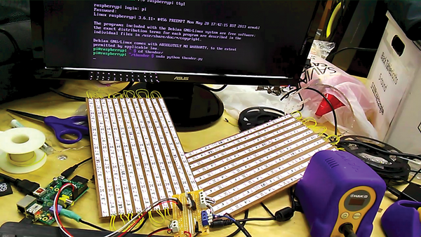 Figure 6: The finished lightning system fully connected and running on the Raspberry Pi.
Software
The software to create and manage the lightning storm tops out at 63 lines, as shown in Listing 1. Two functions define the lightning behavior: I set up the GPIO, and then the main loop waits for the sensor to be tripped. Next, I'll break down the script line by line.
Listing 1
Thunder.py
01 import RPi.GPIO as GPIO
02 import time
03 import random
04 import pygame
05
06 def strike ( lightning1 , lightning2 , brightness , rumbleBrightness , rumbleLength ):
07    lightning1.ChangeDutyCycle ( brightness )
08    time.sleep ( .03 )
09    lightning2.ChangeDutyCycle ( brightness )
10    time.sleep ( .03 )
11    lightning1.ChangeDutyCycle ( 0 )
12    time.sleep ( .03 )
13    lightning2.ChangeDutyCycle ( 0 )
14    time.sleep ( .03 )
15    rumble ( lightning1 , lightning2 , rumbleBrightness , rumbleLength )
16
17 def rumble ( lightning1 , lightning2 , brightness , cycles ):
18    for i in range ( cycles ):
19       rnd1 = random.randrange ( 0 , brightness )
20       rnd2 = random.randrange ( 0 , brightness )
21
22       lightning1.ChangeDutyCycle ( rnd1 )
23       time.sleep ( .03 )
24       lightning2.ChangeDutyCycle ( rnd2 )
25       time.sleep ( .03 )
26
27    lightning1.ChangeDutyCycle ( 0 )
28    lightning2.ChangeDutyCycle ( 0 )
29
30
31 GPIO.setmode ( GPIO.BCM )
32
33 GPIO.setup ( 8 , GPIO.OUT )
34 GPIO.setup ( 25 , GPIO.OUT )
35
36 GPIO.setup ( 7 , GPIO.IN , pull_up_down=GPIO.PUD_UP )
37
38 lightning1 = GPIO.PWM ( 8 , 500 )
39 lightning2 = GPIO.PWM ( 25 , 500 )
40
41 lightning1.start ( 0 )
42 lightning2.start ( 0 )
43
44 pygame.mixer.init()
45 pygame.mixer.init()
46
47 thunder = pygame.mixer.Sound ( "thunderBass.wav" )
48
49 while 1:
50    while ( GPIO.input ( 7 ) == 1 ):
51       pass
52
53    time.sleep ( 5 )
54    thunder.play()
55    time.sleep ( .7 )
56    strike ( lightning1 , lightning2 , 100 , 40 , 20 )
57    time.sleep ( .2 )
58    strike ( lightning1 , lightning2 , 50 , 20 , 10 )
59    strike ( lightning1 , lightning2 , 25 , 10 , 50 )
60    strike ( lightning1 , lightning2 , 100 , 5 , 75 )
61    strike ( lightning1 , lightning2 , 75 , 5 , 200 )
62
63    time.sleep ( 15 )
PWM
PWM (for Pulse Width Modulation) is a way of simulating analog values from a digital source. To generate PWM, you first decide on a PWM frequency. In this program, that's the 500Hz that gets supplied to the PWM function. It means that the cycle will repeat 500 times per second.
A PWM signal is digital. It's either completely on or completely off. Different simulated analog values are created by changing (modulating) the duty cycle, or how long the pulse is on each cycle. A duty cycle of 50 percent means that the output will be HIGH for half of the time, and LOW for the other half. For lighting, this will result in illumination at approximately half of the total possible output level.
Dimming lighting works well this way, and even motors can handle PWM signals. By adding a capacitor to a PWM output, you can actually generate variable voltage signals as well, if that's what your project requires.
Buy this article as PDF
Pages: 5
(incl. VAT)
Buy Raspberry Pi Geek
US / Canada
UK / Australia
Related content
-
Roasting beans in a repurposed air popper

Transform an old air popcorn popper into a coffee bean roaster controlled by a Raspberry Pi and a slick user interface.
-
Protect your electronics from lightning strikes

Add a lightning detector to your vulnerable projects via the I2C bus to protect them from electrical storms.
-
A new way of no-solder prototyping

The Grove system's standardized connector and multitude of devices allow quick and easy project prototyping with your favorite small-board computers.
-
Adding analog input to the Pi using the Digispark

Analog input needs special treatment in the digital Raspberry Pi world. We show you what you need to do to get analog data into your Rasp Pi via the USB port.
-
SunRover Part 4 – Adding a Pi Camera and Diagnostics System

A Raspberry Pi Camera module and a diagnostics system allows SunRover to see and check that all systems are go.
