Fast clocks, model railroads, LED displays, and more
3.3V versus 5V
Even though the Pi Zero (and all Pi products) operate their GPIO at 3.3V, that's enough to show a "high" level to the 5450 – even when it is operating at 5V. The 5450 considers anything over 2.2V as high. If the 5450 needed to send data back to the Zero, then the voltage would need to be lowered first. Otherwise, the GPIO on the Pi Zero would be damaged.
Each remote display requires four seven-segment displays (seconds are not included on remote displays), one MM5450, and a board to wire it all together (Figure 2). Wires for ground, clock, and data connect to the Pi Zero. For power, you can either use a fourth wire to get power from the Zero or provide a local power source at each display (Figure 3).
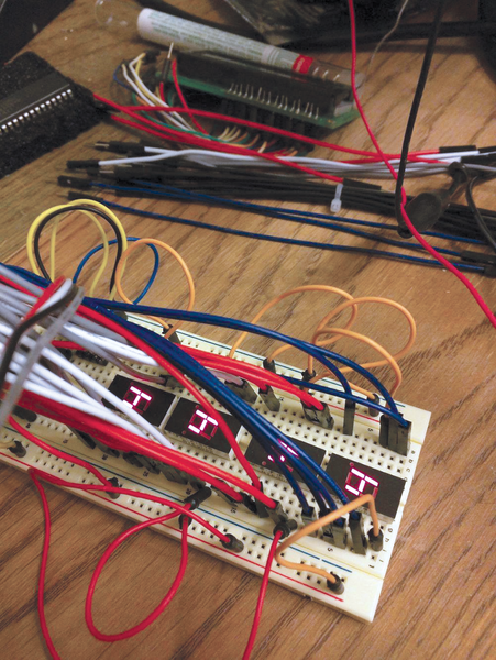 Figure 2: This is the display circuit on a breadboard, currently displaying 4s. The wiring partially obstructs the displays.
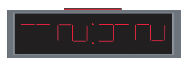 Figure 3: On my breadboard, the displays are rotated 90 degrees counterclockwise, which makes a digital clock look like this.
This setup can be repeated at multiple locations wherever you want a remote display. Lines can "daisy chain" from the previous display or have their own run back to the Pi Zero.
Common Anode versus Common Cathode
One of the "gotchas" of electronics is how components are wired inside of a chip or physical package. It is not practical to bring both the positive and negative leads of seven-segment displays out to breadboard pins, so one side is wired together internally. Common anode wiring connects all of the positive sides together and brings them out to one or two pins. Common cathode wiring connects all of the ground sides together (Figure 4).
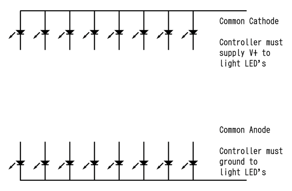 Figure 4: The difference between common anode and common cathode wiring. Displays often come in both varieties and physical appearance is usually identical, with the only difference being the part number.
The MM5450 is known as a current sinking device because it either allows current to flow to ground or not. Because ground is being switched, this project requires a common anode display – all of the positive leads wired together.
« Previous 1 2 3 4 Next »
Buy this article as PDF
Pages: 8
(incl. VAT)
Buy Raspberry Pi Geek
US / Canada
UK / Australia
Related content
-
Touchscreen audio controller for presentation sound

At the Fort Worth Museum of Science and History's Noble Planetarium, one Raspberry Pi has replaced four CD players for various music and sound effects.
-
Using a temperature and humidity sensor to monitor a terrarium

An Arduino sensor, a Raspberry Pi, and a Python program help a budding naturalist keep tabs on the conditions in his snake's terrarium.
-
Pygame modules for interactive programs

Pygame modules are particularly suited to programming highly interactive software. We look at the modules dedicated to events, sound, and input by keyboard, mouse, and game controller.
-
Graphical displays with Python and Pygame

As its name implies, Pygame is a set of Python modules designed to write games. However, many Pygame modules are useful for any number of projects. We introduce you to a few Pygame modules that you can use to create custom graphical displays for your project.
-
Use an analog sensor as a video game controller

We put our Analog-to-Digital converter to work reading positions from an analog sensor (a potentiometer) and control a bat in a simple implementation of the classic Breakout game.
