Atmel power control for a Lionel train

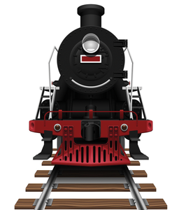
Lead Image © tshooter, 123RF.com

Train Power

The accessories, signals, and towns come to life on my Lionel train layout with the help of sensors, detectors, lots of relays, and Linux control software. The trains, though, remain strictly under human control. This year that's about to change!

In the world of Lionel, "train power" isn't limited just to the trains themselves. Electric switches that can be thrown by remote pushbuttons (Figure 1) and uncoupling magnets (Figure 2) are the prime examples. These two devices, part of the track itself, come with the "common" wire connected to the outside rail.

Figure 1: A Lionel electric switch. Note the wire coming out through the housing. This is the common wire. The screw terminals are for pushbutton connections.
Figure 2: An uncoupling magnet track (bottom view). Note the solder joint where the common was previously connected. Although electrically convenient, the barrier strip can sometimes snag trains as they pass.

Although it is possible to break this connection, often it is not practical. The accessory is designed for a button to connect the device and the inner rail, so the easiest way to activate these devices is still with the track power itself.

The accessories usually run on the same voltage levels as the track and are designed to be powered by the same throttle, but strictly speaking, track connections are not required. I try to keep them separate as much as possible.

Lionel Power and Direction

Lionel trains [1] take a unique approach to power distribution. This is most obvious in the track itself, which has three rails instead of two. The outer rails are connected and the single center rail provides the opposite pole. Pre-war Lionel trains have a standard operating voltage of 18VAC. More modern trains are universal, so they'll operate on AC or DC.

On smaller model trains (e.g., HO and N scales), the direction is controlled by the polarity of the voltage on the rails. Lionel trains simply switch direction every time power is applied. On very early equipment this was controlled by a physical rotary switch that rotated 180 degrees each time power was applied. Newer equipment now controls the direction electronically and adds a neutral position. Therefore, the cycle is forward – neutral – reverse – neutral – and so on. A switch hidden on the engine allows it to be locked into "forward only" for displays or continuous loops.

In years past, the path of train power to track has been through a maze of switches, buttons, and barrier strips. Figure 3 shows some of the control boxes I built as my layout grew. When a local music supplier went out of business, I visited their closeout sale, and one thing I found was a box filled with large power relays that controlled jacks on the side of the box. The store manager explained that it was the heart of the demo system that allowed a customer to select an amplifier/speaker combination and hear how it sounded. He also explained that it was 75 percent off, so I acquired it for about US$ 20.

Figure 3: Control boxes for different train power configurations.

The box didn't have a controller, just the relays themselves (Figure 4), so that's where my project began: How to control 24 relays from a computer and make it talk to the existing control software (see the "Throttles, Blocks, and Relays" box).

Throttles, Blocks, and Relays

The terms throttle, transformer, and cab are used somewhat interchangeably, but ultimately they are a box that plugs into the wall and provides variable AC power up to about 18V to drive a train. A small train layout might have only one box, but this grows quickly with the layout. My layout uses three boxes: Two are for the main line and sidings, and the third is dedicated to a trolley line that doesn't connect with the rest of the layout.

A block is a section of the railroad that is electrically isolated. Each siding is usually a separate block so that its power can be switched off independently; then, any trains parked there will stay put. The mainline itself is usually divided into multiple blocks. Each block can receive its power from either of the mainline throttles. In this way the layout can be sectioned off so that multiple trains (two in my case) can operate independently.

To accomplish this, each block is controlled by two relays wired in a cascading fashion – the first relay feeds into the second (Figure 5). If neither relay is active, then no throttle is connected, and the block is off. Whenever one relay or the other comes on, then that throttle's power is routed to its associated block. The control software makes sure that both relays aren't activated at once. This is repeated for each block on the railroad.

Figure 4: Relays for block control in their partially rewired state. The extra wires are for testing as the electronics are developed.
Figure 5: The wiring diagram of the relays, track, and driver board.

The Relay Driver Board

The purpose of the relay driver board is to be a bridge between the electronics and the computer. On the electronics side, it has to have components appropriately sized to switch the relays on and off. That interface then has to receive commands from the computer – which relays to turn on and off.

A microcontroller is a single-chip computer. Out of the package, it doesn't do anything; you write custom firmware (software for an embedded processor) to tell it what to do. My software listens for serial commands and uses those commands to turn the relays on and off.

Buy this article as PDF

Express-Checkout as PDF
Price $2.95
(incl. VAT)

Buy Raspberry Pi Geek

SINGLE ISSUES
 
SUBSCRIPTIONS
 
TABLET & SMARTPHONE APPS
Get it on Google Play

US / Canada

Get it on Google Play

UK / Australia

Related content