No Worries
A sudden loss of power can create critical problems for many applications. To avoid such outages, the Raspberry Pi has a proper uninterruptible power supply.

Lead Image © David Grigg, 123RF.com
A sudden loss of power can create critical problems for many applications. To avoid such outages, the Raspberry Pi has a proper uninterruptible power supply.
Normally, a battery or a rechargeable power pack is sufficient when running a computer; however, an uninterruptible power supply (UPS) is even better. This article explores some of the capabilities provided by these power supplies.
Starting out with the elegant UPS called UPiS is extremely easy. You don't need to get out the soldering iron to use the UPiS with the Raspberry Pi. This UPS consists of one board connected via the GPIO pins to the Rasp Pi [1] and a lithium polymer (LiPo) battery. One of the delivered components is a piece of double-sided tape used to attach the battery to the UPS.
Once the Raspberry Pi and the UPiS are attached to one another, the setup no longer fits into a standard cover because of the increased size and the need for openings that will accommodate additional connections and switches (Figure 1). Covers for this piggy-back combination are available over the Internet, or you can build one yourself [2].
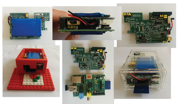 Figure 1: The UPiS comes with additional connections and switches. Although it fits nicely on the Raspberry Pi, the combination of the two devices is too big for a standard cover.
Incidentally, two versions of the UPS are available: basic and deluxe [3]. These two versions are almost identical in shape but the deluxe version has a larger battery, two voltage inputs, and offers more functionality. However, the basic version is still impressive enough to serve as the foundation for this article. You can explore the differences between the two versions in more depth in the UPiS manual [4] and FAQ [5]. In the meantime, the important characteristics of the UPS are as follows:
The UPS can only assume the task of supplying power if the Raspberry Pi has already been started. A successful boot must therefore draw power from an electrical outlet. The basic setup is quick. All you have to do is connect the UPS board with the LiPo battery, plug it into the nano-computer, connect the power supply, and presto! From then on, the UPS will continuously monitor whether current is being drawn.
The battery should be charged before running tests for the first time. If the external power supply goes out, the little ARM computer will continue to run for two more hours. However, the operating system of the Raspberry Pi will not notice a transfer to battery power unless additional measures are put in place. It is easy and convenient to read the current condition of the UPiS via the I2C bus [6] [7].
You should first check the firmware for the UPiS board and update it if necessary. You would have needed a Windows system if you were doing this before September 2014. Since then, it has become possible to update directly from the ARM computer provided you make some manual adjustments.
Communication takes place over the serial interface of the UPS, which needs to be accessible from the Raspberry Pi. Access is established by re-setting two jumpers of the UPiS. Details for doing this are found in the user handbook [4] under "Route Raspberry Pi RS232 to UPiS Serial Port."
Users should test the setting of the jumpers and whether the so-called UPiS terminal commands work properly (Listing 1) before updating the firmware. You should begin all UPiS commands with the @ character so that the UPS board recognizes them. All of the commands are described in the user handbook.
Listing 1
Terminal Commands
01 $ minicom -b 38400 -o -D /dev/ttyAMA0
02
03 @version
04
05 www.pimodules.com
06 Upis Basic
07 Firmware Version:1.096 Beta Version
08 Hardware Release:VCO2
09
10
11 @status
12 ...
13 Powering Source:USB
14 Upis RTC Date:2014:10:26
15 Upis RTC Time:12:45:54
16
17 Average Powering Values
18 ----------------------
19 RPi Voltage:05.07 V
20 ...
21 Real Time Clock Correction Factor value is: 0x00
22 Analog Sensor Temperature:43 C 0109 F
23 ...
The second preparatory step is to change the plugin location for the power supply. The micro-USB connection on the Raspberry Pi is used for the firmware upgrade because the installation procedure includes a complete reset of the UPiS board, and this step would interrupt the supply of power to the ARM computer. At the end, you should copy the Python script [8] and the firmware to be loaded onto the Pi and install python-serial and python-smbus if needed:
sudo apt-get install python-serial
sudo apt-get install python-smbus
The firmware upgrade itself does not involve doing anything spectacular. To begin, you should put the UPS in the so-called bootloader mode. This is done by pressing and holding the RST button, then doing the same with SDWN. Afterwards, release RST and then SDWN. The status LED on the UPiS should light up in red at this point. If so, you should start the Python script [9] described earlier (Figure 2).
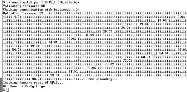 Figure 2: It is recommended that you install the most recent firmware version to avoid errors and to enable activation of additional functions.
Firmware version 1.096Beta was current at the time of writing and is available through the forum [8]. When you order a UPiS board, it will still arrive with version 1.00 of the firmware.
Pages: 6
US / Canada
UK / Australia

When the Raspberry Pi is connected to a car ignition or the USB port on a TV, you run the risk of data loss with a hard shutdown. The Pi UPS bridges short lapses in the power supply and shuts down your Rasp Pi safely when the power remains off.

The resourcefulness of private and commercial users has led to the creation of many practical and novel extensions for the Raspberry Pi. We provide an overview of some useful supplementary circuit boards.

The new Raspberry Pi Model B+ is the biggest change to Raspberry Pi since the Model B Rev 2 upgrade two years ago. Find out what's new with the B+ and how it will affect your Rasp Pi adventures.

Putting power in your robot is more than just running wires – you'll need to make sure the power supply doesn't cause interference that will disrupt other components. This article explores the problem of electrical noise and describes the design for a multiplexing solar power system.

Pulling the plug on your Pi without an orderly shutdown can corrupt the SD card. Also, many users prefer a convenient switch to clicking icons and entering shutdown commands. We show you some options for starting, stopping, and powering down.

Price $15.99
(incl. VAT)