Using logic bits to make decisions

Lead Image © Teguh Mujiono, 123RF.com

That's Logical

One group of littleBits modules allows you to evaluate conditional situations at different points in a circuit without resorting to programming.

The logic modules offered by littleBits include AND, NAND, OR, NOR, and XOR. If you get the Logic expansion pack [1], you also get the Inverter and Latch modules. The logic bits take two inputs and produce a single output that depends on the logic applied. The outcome is mapped in truth tables.

Truth tables map inputs to outcomes, usually as 1s and 0s; however, you can also use true/false, open/close, on/off, or whatever describes your problem. Figure 1 shows truth tables for the logic modules offered by littleBits. Each outcome in the Result column can be expected from the A and B inputs in the same row. In this article, I'll look in particular at the NAND, OR, and Inverter modules.

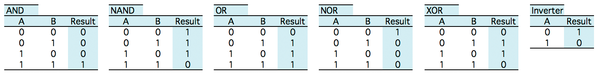
Figure 1: Truth tables for littleBits logic modules.

OR

The OR and AND modules are called double AND and double OR by the littleBits Bitsters because they take two inputs – three- and four-input gates (and even more) are common as well. Here, I'll just refer to them as AND and OR.

OR is a good choice when you just want to detect an input, but you don't care which one. A good example is the alarm system at the Raspberry Pi Geek offices, where the front and back doors sound a momentary alarm (i.e., a discreet beep) to let anyone in the office know that someone is entering or leaving the building. The truth table shown in Figure 2 shows that in any case except two closed doors, the alarm will sound. This is identical to the OR table.

Figure 2: Alarm behavior.

To simulate the door alarms, I attached Roller modules to each input of the OR module, with the output attached to a long LED. Figure 3 shows the circuit with the simulated doors closed and the LED unlit (i.e., no alarm). This circuit includes:

  • Power module (off the bottom of the figure).
  • Split wire, which provides power to both sides of the circuit.
  • Front door roller (right)
  • Back door roller (left).
  • OR module, which sits between the rollers.
  • Long LED module, which indicates when an alarm would sound.
Figure 3: Door alarm circuit with both doors closed.

Figures 4A through 4C show the alarm outcome for various scenarios. Note that this circuit also represents the behavior of a car's dome light: When the driver's door or the passenger's door or both doors are open, the dome light is on, and it won't turn off until all doors are closed.

Figure 4: The alarm sounds (i.e., the LED is on) whether both doors are open (A), only the back door is open (B), or only the front door is open (C).

NAND

NAND simply means "not AND." If you look at the truth tables in Figure 1, you see that the NAND module outputs the exactly opposite outcomes of the AND module, as expected. A popular example of a NAND circuit is the block-out buzzer often used in games that require a player to buzz in first for the chance to answer a question.

NAND is functionally complete (as is NOR) [2], which means all other logic functions can be created by different combinations of NANDs (NORs). In fact, the first flight computer made with integrated circuits (ICs) by NASA for the Apollo program was made entirely of three-input NOR gates [3]. See the "Extra Credit" box for more on functional completeness.

Extra Credit

The illustration at the bottom of this boxout shows one example of functional completeness using only NANDs. An inversion (Inv) is shorthand for a self-NAND (i.e., 0 NAND 0=1 or 1 NAND 1=0). Compare the outcomes to the truth tables in Figure 1. Starting at the top left and moving right, a single A NAND B produces the NAND outcomes; invert that to get the AND results of the starting data set. Returning to the top left, inverting both inputs first (bottom left) then NANDing produces the OR outcomes. Simply inverting the OR gives you NOR. If you NAND the outcomes from the NANDs of the original data set and the inverted data set (the NAND and OR in the center), you get the XNOR results, which when inverted, produces the XOR result. As an exercise, you can try to create all logic outcomes using only NORs.

The block-out buzzer requires a circuit for player A, a circuit for player B, and a way for the two circuits to exchange information. The circuit for player A (Figure 5) includes:

  • Power
  • Button
  • NAND
  • Branch
  • Inverter
  • Bright LED
  • Wire
Figure 5: The circuit for player A with the NAND module.

Normally, the circuit for player B would look exactly the same. However, I only had one NAND module, so I had to use an AND and an Inverter instead. Figure 6 shows this modified circuit, which includes:

  • Power
  • Button
  • AND
  • Branch
  • LED
  • Wire
  • Inverter
Figure 6: The circuit for player B with the AND and Inverter modules to create a NAND outcome.

When player A presses the button (1) in the absence of a button press from player B (0 inverted to 1), the truth table informs you that it outputs a no-press signal (1 NAND 1=0). At the branch, this 0 is sent to the Inverter, which reverses it to a 1 and lights the LED, as well as to player B's circuit.

When player B presses the button (1), the AND module, in the absence of a signal from player A (1 from the NAND), outputs a button press (1 AND 1=1), turning on the LED, and inverts the 1 to a 0 before sending it to player A.

If a button press from player B (1 inverted to 0) is already waiting at the NAND when player A presses the button (1 NAND 0=1), the output is inverted to a 0 farther down the circuit, and the LED stays unlit. You can trace every scenario through these connected circuits with the help of the truth tables. Better yet, you can build the circuits and test them yourself.

Figure 7 shows the circuits of players A and B connected. Notice that I only had one Branch module; however, because I only needed two of the three Branch outputs, I could use the Split wire to send the signal to the LED and player A's circuit.

Figure 7: The complete block-out buzzer.

Buy this article as PDF

Express-Checkout as PDF

Pages: 4

Price $2.95
(incl. VAT)

Buy Raspberry Pi Geek

SINGLE ISSUES
 
SUBSCRIPTIONS
 
TABLET & SMARTPHONE APPS
Get it on Google Play

US / Canada

Get it on Google Play

UK / Australia

Related content