Using logic bits to make decisions
The logic modules offered by littleBits include AND, NAND, OR, NOR, and XOR. If you get the Logic expansion pack [1], you also get the Inverter and Latch modules. The logic bits take two inputs and produce a single output that depends on the logic applied. The outcome is mapped in truth tables.
Truth tables map inputs to outcomes, usually as 1s and 0s; however, you can also use true/false, open/close, on/off, or whatever describes your problem. Figure 1 shows truth tables for the logic modules offered by littleBits. Each outcome in the Result column can be expected from the A and B inputs in the same row. In this article, I'll look in particular at the NAND, OR, and Inverter modules.
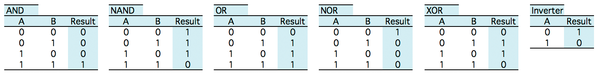 Figure 1: Truth tables for littleBits logic modules.
[...]
Buy this article as PDF
Pages: 4
(incl. VAT)
Buy Raspberry Pi Geek
US / Canada
UK / Australia
Related content
-
littleBits modules quickly create a colorful and animated Christmas scene

The Christmas season is full of music, lights, and animated scenes of the holiday. What better time to put your open hardware to work at home?
-
Control your littleBits projects with a homemade wireless remote

Make a custom handheld wireless remote control with littleBits Wireless Transmitter and Receiver bits and slider, knob, button, or toggle bits.
-
Make an Android phone app to control your littleBits projects

Make a remote control paddleboat with the littleBits Arduino module, DC motors, and generic Bluetooth module and control the boat with a phone app that uses the MIT App Inventor package.
-
Open doors with a Raspberry Pi and RFID module

A Raspberry Pi combined with an RFID module can open doors automatically, but only if proper access rights are presented.
-
Find out how fast you can run

Time your sprints over and over again, so you can track your improvement.
