Using the ESP8266 as a micro-controller for servomotors

Lead Image © realmccoy, 123RF.com

Hands On

With an ESP8266 and a few components, you can put together your own robot arm.

The ESP8266 is an extremely versatile chip. One of its many uses includes controlling servomotors. By way of example, during one of our workshop sessions we took some circuit boards and put together a robot arm, which in this project will attempt to solve the "Tower of Hanoi" puzzle (See box out: Until Doomsday)

Until Doomsday

The "Tower of Hanoi" is a mathematical puzzle devised by a French mathematician. The game involves three rods and a number of disks of varying sizes. The puzzle begins with all the disks stacked in size order on one rod. The aim of the puzzle is to move the entire stack of disks to another rod, one disk at a time. Only the upper disk can be removed from any stack and a larger disk cannot be placed on top of a smaller one. As long as there aren't too many disks, this is quite simple to do. The number of moves required to finish the puzzle is 2n-1 where n is the number of disks.

Legend has it that there's an ancient temple in India where Buddhist Monks play this game using 64 sacred disks. The Legend also claims that if the Monks were to succeed in finishing the game, the world will end. However, as per the above formula, this would require just under 18.5 trillion moves. At a rate of one move per second, this would take around 585 billion years, so it's safe to say that the Apocalypse is some time away.

Getting Started

A rudimentary robot arm requires at least four planes of movement: one at the very base to rotate the robot itself, and three in the arm to move it to different positions. Figure 1 shows a simplified diagram for this model.

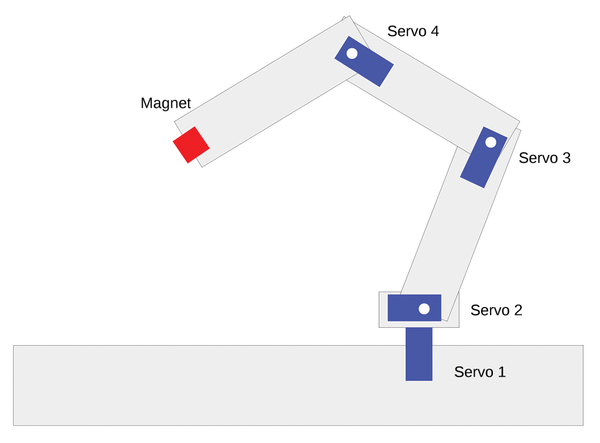
Figure 1: This plan for a robot arm is extremely simplified but shows the basic components you need to make it moveable.

Figure 2 shows the robot arm after assembly. This one was mostly made from leftover circuit boards, which are durable and easy to assemble without specialist tools. The electromagnet at the end of the arm comes from a 5-volt relay we found in an old box of assorted components.

Figure 2: This robot arm, assembled from leftover components, won't be winning any design awards anytime soon, but will do the job.

The base of the robot arm is made from leftover plywood. The servos are the only parts we purchased. Even if you don't have an ESP8266, you can buy this and all the other components online for less than 23 dollars. After that, you only need to invest a small amount of skill and time to have your own robot arm.

Servomotors

The servomotors used for this project are tiny ones designed for models rather than the large industrial versions you might find in a car factory. To satisfy any pedants who may be reading, these mini-servos are technically electronically controlled actuators rather than motors, as they're made of several components.

You'll be using an electronic pulse to set the angle of the levers attached to each servo. Each servo has a position sensor which indicates when a lever is straight. The current position of the lever is continuously compared to the desired one and the servomotor moves accordingly, reducing the difference between the two to zero. The motor inside the servo is connected to a mini gearbox to make this happen.

Taking all of this in may seem quite complex, so it's best to focus on the three most important characteristics of a servo, which are:

  • The maximum angle to which a lever connected to a servo can extend.
  • The force applied by the servo.
  • How quickly a servo can change position.

Needless to say, a servo with genuine ball bearings and a metal gearbox is going to be far superior to one made from plastic with plain bearings. However, these also cost more. When getting servos to interface with the ESP8266, use inexpensive components to begin with [1].

You should not just look at the design and characteristics of the servos, but also take a look at the control signal. Servos are controlled by PWM (Pulse Width Modulation) signals. This means that the signal always has the same frequency – only the ratio between the pulse (operating voltage) and pause (length) of the signal varies.

The complete signal has a length of approximately 20 milliseconds. Many servos can reduce this to 10 milliseconds if necessary. Each pulse lasts 1 to 2 milliseconds. The angle of the servo depends on the pulse length. Figure 3 illustrates this function (see also the Warning box out).

Figure 3: To control a servo, you need a PWM control signal. The longer the pulse, the greater the servo angle.

Warning

The levers automatically move to the zero degree position when the servos are initialized. As such, the arm may knock things off your work surface, so be sure to remove anything fragile beyond its reach. If you've built an arm that extends beyond your work surface, make sure to keep people and pets away too.

Buy this article as PDF

Express-Checkout as PDF

Pages: 8

Price $2.95
(incl. VAT)

Buy Raspberry Pi Geek

SINGLE ISSUES
 
SUBSCRIPTIONS
 
TABLET & SMARTPHONE APPS
Get it on Google Play

US / Canada

Get it on Google Play

UK / Australia

Related content