Exploring the new Arduino/Genuino 101
Intel has been maneuvering to open up a niche for itself both in the nanocomputer space (currently dominated by the ARM-based Raspberry Pi) with its Edison [1] and in the realm of microcontroller-based maker hobbyism ruled by the Arduino and Arduino-like hardware, which is typically designed around the ATmega chips built by Atmel.
The 101
To try to get a foot in the door in the latter camp, Intel and Arduino recently teamed up and produced the Arduino 101 [2]. The 101 looks very much like the Uno (Figure 1), and, in many respects, it is compatible. Even the mount holes for screws are in the same place.
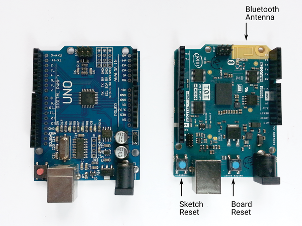 Figure 1: The Uno (left) and the new 101 (right), with its rather conspicuous Bluetooth antenna in the upper right-hand corner and two reset buttons at the bottom.
101 Setup
Arduino boards with special features often require special setups, which is the case with the 101. To begin, you'll need the recent version of the Arduino IDE, namely 1.6.7 (at the time of writing) or higher. This is unfortunate, because it means you will not be able to program the 101 from the Raspberry Pi: The Pi's repositories come with a much older version, and there is no easy way to compile the latest Arduino IDE source code for Raspbian.
But, hey, version 1.6.7 is available for GNU/Linux 32 and 64 bits, Windows, and Mac OS X. I'm using Linux, so I'll go with that for these examples.
Download the latest version of the IDE [5], install it, and fire it up. Go to Tools | Board: [name of the board you last used] | Boards Manager. Scroll down until you see the Intel Curie Boards option. Click on it then on Install. Once the download and installation is complete, the Arduino 101 will appear on your board list (Figure 2).
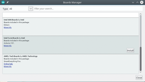 Figure 2: Before you can use your 101, you have to install support for Intel Curie-based boards.
In this article, you'll be seeing a project that uses the 101's gyroscope (I'll exploring other features of the 101 in future articles), so you'll also need the Madgwick library [6]. This library contains functions that turn the raw data from gyroscopes and accelerometers into something intelligible – into numbers you can actually use. To install the library, go to Sketch | Include Library | Manage Libraries and use the search box to narrow down the list (Figure 3).
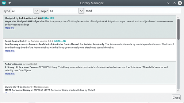 Figure 3: Install the Madgwick library so you can make sense of the data the gyroscope sends you.
Finally, as the gyroscope gives you information about its orientation in 3D, you will use it to control an object on your screen in 3D. For this, you will be using Panda3D [7], a seriously cool 3D library for Python that lets you create and animate 3D objects (see the box "Installing Panda3D" for more information).
Installing Panda3D
You could install Panda3D from your repositories. Just use your software manager and search for "panda3d" and most Linux distributions will do all the dirty work for you. But, where's the fun in that? Most distros have editions that are at least three version old, and that is unacceptable, so I'll show how to install from source.
The creators of Panda3D recommend you install a series of packages before you attempt to compile the package. For Debian/Ubuntu-like distros, they recommend you run the commands shown in Listing 1.
After that, you can download the source code for Panda3D using:
$ git clone https://github.com/ panda3d/panda3d.git
Move into the panda3d directory that the instruction above creates, and run the following:
$ python<X> makepanda/makepanda.py --everything --installer --no-egl --no-gles --no-gles2
Where python<X> is the version of Python you want to use with Panda3D.
The compile starts and will probably show some warnings alerting you to missing dependencies. You have the choice of stopping the compile then and there by hitting Ctrl+C and hunting through your distro's repositories for the packages it asks for or just ignoring the warnings. The dependencies it complains about are very specific and for special cases only. They are things you'll probably never miss, so it is safe to proceed without them.
The compile takes a while. Actually, it takes a long while. But, when it's done, you can use:
$ sudo python makepanda/installpanda.py
to copy the files to the right places.
After installing, remember to run ldconfig as root so the system is aware of where the Panda3D libraries are installed.
By the way, you will not be able to compile Panda3D for the Raspberry Pi. It takes up too many resources and ends up freezing the Pi. As with the latest version of Arduino, this only works on a regular, x86-based computer.
Listing 1
Install Packages
$ sudo apt-get update
$ sudo apt-get upgrade
$ sudo apt-get install build-essential pkg-config python-dev
  libpng-dev libjpeg-dev libtiff-dev zlib1g-dev libssl-dev
  libx11-dev libgl1-mesa-dev libxrandr-dev libxxf86dga-dev
  libxcursor-dev bison flex libfreetype6-dev libvorbis-dev
  libeigen3-dev libopenal-dev libode-dev libbullet-dev
  nvidia-cg-toolkit libgtk2.0-dev
Gyrating Helicopters
Next, I'll show how you can initialize and read from the 101's onboard gyroscope. Take a look at Listing 2. It might look complicated, but it is really the two libraries brought in on lines 1 and 2 that do the heavy lifting. CurieImu.h contains the Arduino 101's specific libraries and Madgwick.h contains, as explained above, the functions that help turn the gyroscope's input into usable data.
Listing 2
gyro.ino
01 #include "CurieImu.h"
02 #include "MadgwickAHRS.h"
03
04 Madgwick filter;
05
06 int gx, gy, gz;
07 int yaw;
08 int pitch;
09 int roll;
10 int factor = 800;
11
12 void setup() {
13   Serial.begin(9600);
14
15   CurieImu.initialize();
16
17   if (!CurieImu.testConnection()) {
18     Serial.println("CurieImu connection failed");
19   }
20
21   Serial.print("Starting Gyroscope calibration...");
22   CurieImu.autoCalibrateGyroOffset();
23   Serial.println(" Done");
24
25   Serial.println("Enabling Gyroscope offset compensation");
26   CurieImu.setGyroOffsetEnabled(true);
27 }
28
29 void loop() {
30   gx = CurieImu.getRotationX();
31   gy = CurieImu.getRotationY();
32   gz = CurieImu.getRotationZ();
33
34   filter.updateIMU(gx/factor, gy/factor, gz/factor, 0.0, 0.0, 0.0);
35
36   yaw = int(filter.getYaw()*100);
37   roll = int(filter.getRoll()*100);
38   pitch = int(filter.getPitch()*100);
39
40   Serial.print(yaw); Serial.print(" ");
41   Serial.print(roll);Serial.print(" ");
42   Serial.println(pitch);
43   delay(10);
44 }
Note that line 4 creates a Madgwick object called filter that is used on line 34 to convert the raw data incoming from the gyroscope. Lines 6 to 10 initialize some variables: gx, gy, gz will contain the data culled from the gyroscope, which will be processed and ultimately passed on into the yaw, pitch, and roll variables (see the "Yaw, Pitch, and Roll" box for details). Finally, the factor variable is used to dampen the gyroscope's sensitivity.
Yaw, Pitch, and Roll
Yaw, pitch, and roll (Figure 4) are the proper names of the axes around which a 3D object can rotate. If you think of a road as a flat 2D surface, a car only has yaw, meaning it can turn only left or right. An airplane, however, can move on three axes. It can turn left and right, rotating on its y-axis (yaw). It can dive or climb by dipping or rising its nose, rotating on its x-axis (pitch), and it can rotate along its z-axis, dipping one wing while raising the other (roll).
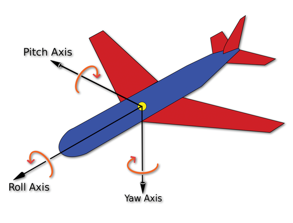 Figure 4: The three types of rotation on a 3D body. (CC BY-SA 3.0) [8]
This sketch's setup() first opens a Serial connection back to the computer on line 13. You're going to read the gyroscope's output over that channel later. After that, a connection is opened to the gyroscope on lines 17 to 19, and the gyroscope is calibrated on line 22. While this is happening, the 101 should be resting on a flat surface and pointing in the direction you rule as "front," because that is what the 101 is going to consider the starting position.
The gyroscope starts measuring as soon as its offset is enabled on line 26. Down in the loop() section, the first step is to read in the relative rotation of the three axes (lines 30 to 32). Note how the names of the CurieImu library are quite self-explanatory.
Next, the data is converted to something usable with the Madgwick functions (lines 34 to 38). Unless you want to get into the math and physics of how you filter inertial and inertial/magnetic sensor arrays [9], you'll just have to trust the Madgwick library on this one.
The last three parameters of the updateIMU() function, the 0.0s, would usually contain data incoming from the accelerometer. As you are only going to use the rotation data, you don't need them.
Then, the yaw, pitch, and roll data is pushed through the serial channel to the computer (lines 40 to 42). Each rotation value is separated with a space, because that's the easiest way to process the line when you read it from Python on the computer. Finally, the script pauses a bit at the end (line 43).
You can run this code without anything else. Plug in your 101, choose it from the Tools | Board: drop-down menu, then upload the sketch to your Arduino (you can see the progress in the console at the bottom of the Arduino IDE) and wait about five seconds for the 101 to restart with the new sketch. Next, click on Tools | Serial Monitor (Figure 5). Pick up your Arduino and move it around. You should see the numbers change depending on the board's rotation.
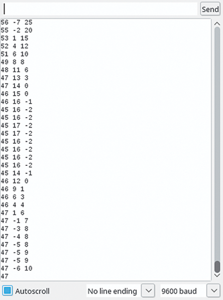 Figure 5: Wave your 101 around and watch the rotation values change.
3D Pandas
Now, I'll get down to the task of showing the effects of rotating the 101 in a more visually appealing way.
As a Raspberry Pi user, you are probably familiar with Python. Although you can find several 3D engines, Panda3D is probably one of the most powerful ones for Python. Besides, it makes rendering and moving a 3D object around very simple (see the "From Blender to Panda" box for more info).
From Blender to Panda
You can of course write code that will render an object in Panda3D programmatically, but writing a program that generates anything more complex than a cube is a pain. Usually, you would create an object in a visual 3D editing application, such as Blender [10], save it in some standardized format, and then convert it to the EGG format Panda3D understands best. That is how the helicopter in this article was created.
You can download the original model online [11]. The archive file comes with the mesh in several formats, one of which is for Blender. Open the file in Blender, delete all unnecessary elements (cameras, lights, floor, etc.) and make the chopper green, because … reasons.
Since Panda3D doesn't support importing directly from Blender, the documentation recommends saving the mesh as a DirectX object. Go to File | User Preferences and, in the dialog that opens, click the Import-Export button to narrow things down. Scroll down until you see the Import-Export DirectX X Format option. Click in the checkbox on the far right. If you're going to do this often, you might want to click on Save User Settings. Either way, when you're done, close the window.
Now you can save the mesh in the X format by choosing the File | Export | DirectX (.x) option and a name and place to put your file.
Panda3D comes with several handy tools to convert from format to format. The one you need to convert to the Panda3D EGG format is called (unsurprisingly) x2egg. So, using a terminal, cd into the directory were you saved your model, and type:
$ x2egg <modelname>.x > <newmodelname>.egg
The truth is, both .x and .egg files are plain text files, containing very similar information – namely, a list of three-number series that represent vertexes and instructions on how to apply textures, only in a slightly different order. All x2egg does is reformat the data for the egg.
Once you have your .egg file, you can import it into your program as shown in Listing 3.
Listing 3
copter.py
01 from direct.showbase.ShowBase import ShowBase
02 from direct.task import Task
03 from panda3d.core import *
04
05 import serial
06
07 class MyWindow(ShowBase):
08     def __init__(self):
09         self.ser = serial. Serial('/dev/ttyACM0', 9600)
10
11         ShowBase.__init__(self)
12
13         base.disableMouse()
14
15         alight = AmbientLight('alight')
16         alight.setColor(Vec4(0.4, 0.4, 0.4, 1))
17         alightNP = render.attachNewNode(alight)
18         render.setLight(alightNP)
19
20         plight = PointLight('plight')
21         plight.setColor(VBase4(1, 1, 1, 1))
22         plNP = render.attachNewNode(plight)
23         plNP.setPos(10, 10, 0)
24         render.setLight(plNP)
25
26         self.copter = self.loader.loadModel("0000_MyModels/helicopter.egg")
27         self.copter.setScale(1, 1, 1)
28         self.copter.setPos(0, 20, 0)
29         self.copter.setHpr(0, 0, 0);
30         self.copter.reparentTo(self.render)
31
32         self.taskMgr.add(self.rotate_copter, "Rotate Copter")
33
34     def get_YPR(self):
35         self.Hpr=[int(i) for i in self.ser.readline().split()]
36
37     def rotate_copter(self, task):
38         self.get_YPR()
39         self.copter.setHpr(self.Hpr[0],self.Hpr[1],self.Hpr[2]);
40         return Task.cont
41
42 if __name__ == '__main__':
43     win = MyWindow()
44     win.run()
As a proof of how easy Panda3D is, take a look at Listing 3. It is grand total 44 lines long, including empty lines, and it is all you need to read in the data from the Arduino and jiggle a 3D model of a helicopter around, depending on the rotation of the gyroscope (Figure 6).
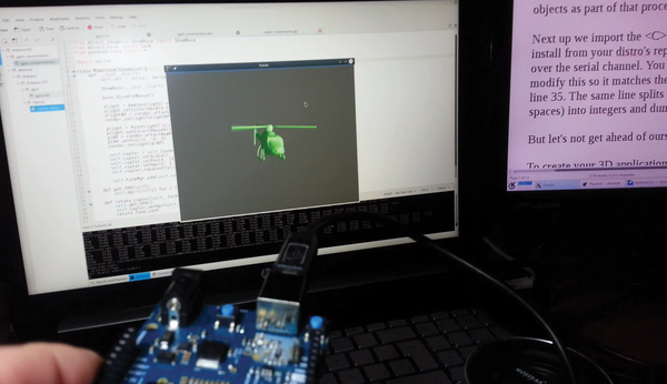 Figure 6: Wave your 101 around and watch the chopper bank and spin!
To start, on lines 1 through 3, you bring in some Panda3D-specific modules. Because you have to show your 3D objects somewhere (e.g., a window), Panda3D provides a class that builds a window. The ShowBase module provides a framework for that. When ShowBase.__init__(self) is called on line 11 (i.e., when a ShowBase object is initialized), Panda3D automatically creates a window for your 3D objects as part of that process.
Next up, the serial module is imported on line 5. This is a Python module you may have to install from your distro's repository, but it will let you communicate easily with the Arduino 101 over the serial channel. On line 9, I create the serial object ser (note that you may have to modify this so it matches the port your 101 is assigned – look in your /dev directory), and this will be used later to read the input on line 35. The same line splits the input (which comes in as a string of characters, the data itself separated by spaces) into integers and dumps it into the object's Hpr attribute.
But I don't want to get too far ahead.
To create your 3D application/window, you can have the class inherit ShowBase (line 7) and then initialize the Panda3D window from within the initialization method of the child class (line 11).
The next thing to do is disable the mouse control in your window (line 13). With mouse control enabled (which is the default), you can use the mouse buttons and drag to zoom, rotate, and pan your 3D scene. Because you will be using the Arduino 101 to move things around, however, you don't want the mouse interfering, so you can zap it.
Next, you get to create two 3D objects: in this case, two lights. The first, alight, is an ambient light. An ambient light is like the light that bathes real life on a cloudy day. It doesn't seem to come from any particular point (so you don't have to indicate where it is located in the scene). In 3D, it is used to diffuse the shadows projected by other lights that otherwise would be unrealistically sharp. Line 16 sets the color of the light. The four parameters are the light's red, green, blue, and alpha components, so (0.4, 0.4, 0.4, 1) is a muted gray.
Line 17 attaches the light to the scene. Panda3D treats objects in a scene as children of the scene, which can also have their own children. In this case, alight is a child of the scene, so it illuminates all the objects contained within the scene. If it were the child of another object, it would illuminate only that object. Finally, line 18 tells the light to switch itself on by rendering it into the scene.
The block of code from lines 20 to 24 is very much the same, except it describes a point light, which is like a naked light bulb. One difference is that, for point lights, you can set the location (line 23).
At last, I come to the object you want to rotate. As explained in the "From Blender to Panda" box, you can create an object in a 3D editor, such as Blender, convert it to Panda3D's EGG format, and import it into the scene (as on line 26).
Line 27 sets the object's scale. Currently, it's the same size as when it was created. However, you can not only increment the scale of an object across the board but also stretch it or shrink it along any one of its axes. For reference, the x-axis in Panda3D is width (i.e., the axis running from left to right of the window); y is depth, going into the window; and z is height, from bottom to top of the window.
Line 28 sets the object's location in 3D space, in which (0, 0, 0) would be where the viewer is standing. Setting the helicopter's position at (0, 20, 0) places it in front of the viewer, a short distance away.
Line 29 sets the object's rotation. In Panda3D, yaw is referred to as head; hence, setHpr() sets the head/yaw, pitch, and roll in that order.
The last thing you do with the helicopter is reparent it to the scene to display it – that is, attach it as a node to the scene. This, as with the lights, renders the object.
Because Panda3D was designed with games in mind, it comes with a useful feature called tasks. Tasks are operations that you can execute once each frame. All you have to do is add a task to the task manager, and every frame it gets will run until you tell it to stop. You don't have to put it in a loop or anything.
Line 32 shows how this is done: Use the add module to the taskMgr with the name of the function you want to repeat (rotate_copter) and a human-readable name for the task ("Rotate Copter"). The task itself (lines 37 to 40) inherits from the Panda3D task object and, in this case, reads in the rotation values for the Arduino 101 (lines 38 and then 35) and applies them to the helicopter's head, pitch, and roll (line 39). By returning Task.cont (line 40), a Panda3D construct, you ensure the task is executed in the next frame.
You can download all the code for the programs in this article [12] and see the program in action in a video [13].
Conclusion
The 101 is enormous fun. Making a faster, roomier Arduino with only a slight increment in price over the original is already pretty great, but adding Bluetooth and sensors makes the 101 various orders of magnitude better than the Uno. And, it makes creating gesture-enabled interfaces ridiculously simple.
I only have two gripes: The real-time operating system (RTOS) and framework developed by Intel for the Curie chip are not yet open source. At the time of writing (February), Intel says they will open source the code in March [14], but I have seen how companies have often pushed back the date for opening their code again and again, until it has become useless. I hope Intel keeps its promise and completely frees the 101 of proprietary software.
Regardless of whether it does so, however, this is not the open source way. It is already troubling to have Arduino, the flagship enterprise of free hardware, backing a board with a proprietary firmware. However, doubly worrying is the fact that this policy of "closed now, open later" runs against open source principles. The open source way dictates that you should publish soon – bugs and all – and publish often, so others can get in there and help improve your code. Intel's stance on this strikes me as trying to have their cake and eat it, without sharing a slice with anybody else.
My other gripe is that I'd like the 101 to be much smaller. It's current form factor is too unwieldy to fit comfortably into wearables, controllers, or toys. The shape and size of the Arduino Micro – long, narrow, and compact – would be much better (Figure 7).
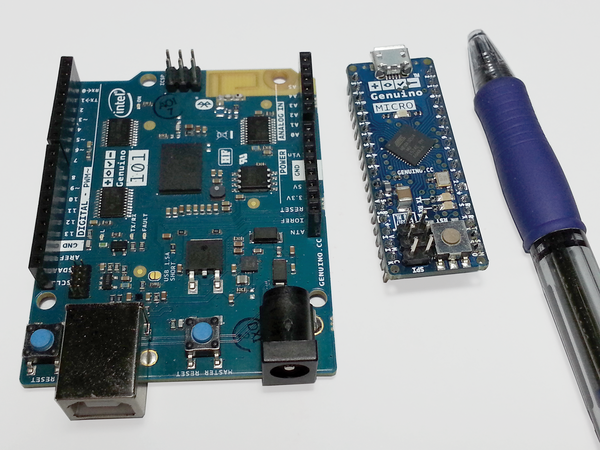 Figure 7: The biggest problem with the 101 is its size. The form factor of the Micro would be ideal for toys, remotes, robots, and wearables.
So Intel, free the Arduino 101 already! Can we haz a 101 Micro, plz?
Infos
- Intel Edison: http://www.intel.com/content/www/us/en/do-it-yourself/edison.html
- Arduino/Genuino 101: https://www.arduino.cc/en/Main/ArduinoBoard101
- "Using an analog port expander, part 1" by Paul Brown, Raspberry Pi Geek, issue 13, 2015: http://www.raspberry-pi-geek.com/Archive/2015/13/Reading-and-writing-from-an-analog-multiplexer
- "Using an analog port expander, port 2" by Paul Brown, Raspberry Pi Geek, issue 15, 2015: http://www.raspberry-pi-geek.com/Archive/2016/15/Write-your-own-drivers-for-Arduino
- Arduino IDE: https://www.arduino.cc/en/Main/Software
- Madgwick's sensor fusion algorithm: http://www.x-io.co.uk/open-source-imu-and-ahrs-algorithms/
- Panda 3D: https://www.panda3d.org
- Auawise, Yaw_Axis.svg, Wikipedia. Attribution-ShareAlike 3.0 Unported: http://creativecommons.org/licenses/by-sa/3.0/
- "An efficient orientation filter for inertial and inertial/magnetic sensor arrays" by Sebastian O.H. Madgwick, 2010: http://www.x-io.co.uk/res/doc/madgwick_internal_report.pdf
- Blender 3D: https://www.blender.org/
- Model helicopter by sielxm: http://tf3dm.com/3d-model/a-low-poly-helicopter-35242.html
- Download the code for this article from GitHub: https://github.com/pbrown66/Arduino-101
- YouTube video showing how the program works: https://youtu.be/JE8npkbd-pU
- Intel to open source the RTOS for the 101 in March 2016: https://www.arduino.cc/en/Main/ArduinoBoard101#overview
[...]
Buy this article as PDF
Pages: 8
(incl. VAT)
Buy Raspberry Pi Geek
US / Canada
UK / Australia
Related content
-
Distributed software compilation for the Raspberry Pi

Distributed compiling with distcc offloads the CPU-intensive compilation tasks from the Raspberry Pi to other computers, saving you days of time and frustration.
-
Connecting a weather station to your Arduino

After losing one weather station to tropical winds, the author reboots and designs a PCB that connects to an Arduino and monitors weather instruments.
-
Build cool stuff with littleBits, a Pi, and some Lego Bricks

Connect the littleBits Arduino module to a Raspberry Pi and you open a world of projects and a world of fun.
-
Joining Raspberry Pi and Arduino applications with SIMPL

We show how to use the SIMPL messaging toolkit to facilitate communication between Pi programs and Arduino software modules.
-
Automated plant watering with Arduino

House plants are fairly self-sufficient, but they do need certain care from people to survive. With a few Arduino sensors and a little programming, you can take the guesswork out of watering your plants.
