Rover Vision
A Raspberry Pi Camera module and a diagnostics system allows SunRover to see and check that all systems are go.
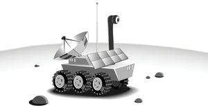
This article is the fourth in a series of articles on building a working solar robot. SunRover is a tracked, solar-powered robot designed to move around and explore while sending back reports, tracking weather, managing a tight power budget, and providing a platform for testing new sensors and equipment as they become available. The motors, the controllers, the computers, and the sensors are all complex devices in their own right.
In Part 1 of this series [1], I went through the motor controller/power system and described the mechanisms for connecting the I2C sensors throughout the robot. In part two [2], I redesigned part of the motor power system and then looked at the solar power charging system, which happily is working perfectly! Part 3 [3] covered the robot's navigation system, and here in Part 4, I look at the Pi Camera system and the I2C diagnostics system.
In this project, I am using a standard Raspberry Pi Camera module as sold by the Raspberry Pi Foundation. This was the same camera I used in Project Curaçao [4], so I know it will handle the heat. The Raspberry Pi Camera module can be used to take high-definition video, as well as still photographs.
The module has a 5-megapixel fixed-focus camera that supports 1080p30, 720p60, and VGA90 video modes, as well as still capture. It attaches via a 15cm ribbon cable to the CSI port on the Raspberry Pi. This cable was too short for SunRover, so I bought a 50cm cable from Adafruit [5]. It's a little tricky to change cables, so be careful. I use the picamera [6] pure Python library for the interface to the Raspberry Pi Camera module.
The code needed to capture a single picture in Python using picamera is simple:
import time import picamera with picamera.PiCamera() as camera: camera.resolution = (1024, 768) camera.start_preview() # Camera warm-up time time.sleep(2) camera.capture('foo.jpg')
For all of you solar power fans, you need to know that the camera uses a lot of current (some report more than 280mA for video and about 150mA for still shots), even when the camera isn't being used. To fix this, issue camera.close()
, and the power drops way down. Note that the example above does not use camera.close()
.
Using a 3D printer, I have built stands, prototypes, bases, and other accessories. The camera base was a natural fit for a 3D printing project. The base would be screwed onto the SunRover box, with a plastic bubble [7] (for water protection, primarily) sitting over the top of the camera that still allowed pan-and-tilt movements (Figure 1). The plastic bubble, although not perfect, has pretty good optics.
The friction-fit stand (Figure 2) has one layer of tape around the base to make it snug, with built-in cableways and slots to mount those boards that need light (color sensors, light sensors, etc.). I also wanted the pan-and-tilt mechanism to fit into the base with no screws.
To date, I have used the slots for two purposes: to mount the superbright LEDs for the camera at night and to mount a compass. Because reflections inside the bubble from the LEDs wiped out the camera image, I instead had to mount the LEDs on the side (Figure 3). The compass mount didn't work too well because it was too close to the pan-and-tilt motors.
On the platform on the front of the robot, I mounted an ultrasonic distance ranger; I will mount the LIDAR laser sensor there in the future, too. Listing 1 shows code for the OpenSCAD platform model. As usual, it is a mixture of cubes, tubes, and blocks. Making similar shapes into modules, then invoking them multiple times, is a great way of reusing code.
Listing 1
OpenSCAD Platform Model
01 // 02 // SunRover Top Bubble Plate 03 // August 2, 2015 04 // SwitchDoc Labs 05 // 06 07 module platform() 08 { 09 10 // slot for LED or board 11 difference() 12 { 13 translate([25,-3,19.9]) 14 #cube([4,6,5]); 15 16 translate([26,-3,21]) 17 cube([1.50,8,10]); 18 } 19 20 translate([23,-10,0]) 21 cube([10,20,20]); 22 } 23 24 union (){ 25 difference() 26 { 27 union() 28 { 29 difference() 30 { 31 cylinder(h=20, r=72.00/2, $fn=100); 32 cylinder(h=22, r=69.55/2, $fn=100); 33 } 34 35 // base plate 36 difference() 37 { 38 translate([-75/2, -75/2,0]) 39 cube([75, 75, 2]); 40 41 // screw holes 42 translate([-68/2, -68/2,-5]) 43 cylinder(h=10, r=2/1, $fn=100); 44 45 // screw holes 46 translate([68/2, 68/2,-5]) 47 cylinder(h=10, r=2/1, $fn=100); 48 49 // screw holes 50 translate([68/2, -68/2,-5]) 51 cylinder(h=10, r=2/1, $fn=100); 52 53 // screw holes 54 translate([-68/2, 68/2,-5]) 55 cylinder(h=10, r=2/1, $fn=100); 56 } 57 58 // camera pylon 59 60 difference() 61 { 62 cylinder(h=50, r=28/2, $fn=100); 63 cylinder(h=55, r=25.25/2, $fn=100); 64 // bar through for wires 65 translate([-6, -20, 2]) 66 #cube([12,40,10]); 67 68 rotate(a=90, v=[0,0,1]) 69 translate([-6, -20, 2]) 70 #cube([12,40,10]); 71 } 72 73 // camera servo nib 74 translate([0,13.5,45]) 75 cylinder(h=10, r=3/2, $fn=100); 76 77 translate([0,-13.5,45]) 78 cylinder(h=10, r=3/2, $fn=100); 79 } 80 translate([0,0,-5]) 81 cylinder(h=10, r=11, $fn=100); 82 } 83 84 platform(); 85 86 rotate([0,0,90]) 87 platform(); 88 89 rotate([0,0,180]) 90 platform(); 91 92 rotate([0,0,270]) 93 platform(); 94 }
Price $15.99
(incl. VAT)