Building the SunRover navigation system

Lead Image © alexandragl, 123RF.com

Pathfinder

The Switch Doc continues his effort to build a solar-powered robot. This month the emphasis is on the navigation system.

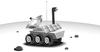
SunRover is a tracked solar-powered robot designed to move around and explore the area while sending back reports, tracking weather, tightly managing a power budget, and providing a platform for testing new sensors and equipment as they become available.

SunRover Robot Philosophy: Yes, I will move around by myself until I get confused or find a cliff. Then I will ask for help from a human. Or at least from a cat.

This article is the third in a series of articles on building a working solar robot. The goal of the series is to explore the kinds of questions you'll need to ask to create your own robot. I'll focus on the process – not just the product, so you can see all the steps that go into the decision process.

SunRover is a big project. The motors, the controllers, the computers, and the sensors are all complex devices in their own right. Part 1 of this series [1] went through the motor controller/power system and described the mechanisms for connecting the I2C sensors throughout the robot.

Part 2 covered the redesign of part of the motor power system and then looked at the solar power charging system, which, happily, is working perfectly [2]! This article is Part 3, and here I'll look at the navigation system for the robot.

Navigation Systems in SunRover

The most critical piece of navigation hardware currently in SunRover is the magnetic compass. And of course, the compass is the sensor I have had the most trouble with.

Earth has a magnetic field. It is quite weak (roughly 25 to 65 microTeslas (uT)) and is roughly 10 degrees offset from the geographic poles (the rotational axis of the earth). Because of the proliferation of drones on the market over the past few years, there has also been a great increase in the number of inexpensive electronic compass I2C modules on the market. These units basically fall into two types:

  • Magnetic field sensors
  • Tilt compensated magnetic field sensors

The magnetic fields sensors, such as the HMC5883L, are very inexpensive. You can pick one up on eBay for less than $5. I first purchased one of these magnetic field sensors to use in SunRover, and I quickly found two issues. One, SunRover tilts – it is on treads, and if it halts suddenly (which is the way the motors usually are shut off), it will tilt. I found the HMC5883L quite sensitive to this tilt, which would vary the compass readings by 15 or 20 degrees magnetic in some cases.

Considering I want to be able to point SunRover to +/- 5 degrees, this tilt was a huge source of error. I did some research, and for about $20, I could get an LSM303D six-axis accelerometer and compass [3]. When the accelerometer came in, I was able to hook it up quickly (you have to love that I2C Grove connector). With that, the tilt issue was fixed.

Next, I noticed that sometimes the compass would lock (at 278 degrees for some reason) when, you guessed it, I ran the motors. Of course, when I needed the heading of the robot the most (when it is moving), the compass would lock. Looking at the data, I surmised that it was primarily the wires running across the unit, with influence from the motors. Until I realized what was going on, the robot would occasionally just sit there and spin until the maximum time expired.

The location in Figure 1 was about 125mm above the motor platform. I then moved it up, to next to the Pi Camera pan/tilt mount (Figure 2), putting it up about 150mm above the motor platform. Well, it looked great, but it would lock up even more regularly because, silly me, it was next to the servo motors driving the PiCamera pan/tilt mount.

Figure 1: First location of the compass.
Figure 2: Second location of compass.

So, even though it looked really cool, I had to move it again. This time, I put it out the side of the robot in a plastic bubble and again it looked great (Figure 3), but it would still lock up occasionally, though not as much as in location 2.

Figure 3: Third location of compass.

Next I started to build a "great tower of magnetic isolation" to put the compass well away from wires and 300mm away from the motors and the PiCamera (Figure 4). Sharp observers will notice that this is the same pylon design used to isolate the Lightning Detector from the computer electrical noise in my recent lightning detection project [4].

Figure 4: Fourth location of compass.

I do think I understand what is going on here, but I'd like a little more science behind what I just did. So, I decided to get an inexpensive (~$100) magnetic field data logger and measure the magnetic currents at all four of the locations (Figure 5). I purchased a NEULOG Magnetic Field Data Logger to get some dynamic readings (and to log them automatically). As of this writing, the NEULOG logger on the Mac Book is not quite ready for prime time. More on the NEULOG loggers in a future SwitchDoc Labs Column.

Figure 5: Logging the magnetic field.

The logger has a resolution of 0.001 milliTeslas (mT), or, in other words, 1 microTesla (uT), so this will allow some really good readings (remember the Earth's magnetic field is about 25--60 microTeslas). Note that the difference (the delta) between static and motors running is the important thing, since the magnetic fields might not be oriented in the same direction (Table 1).

Table 1

DELTA for Static and Motoring States

Compass Location

Static Value (uT)

Peak Absolute Value of DELTA During Motoring (uT)

Control Location Away From Robot

60uT

N/A

Location 1

50uT

9uT

Location 2

187uT

4uT

Location 3

15uT

4uT

Location 4

70uT

1uT

The data shows I was wrong in my assumption that it was motor magnetic noise that was hosing the compass. The problem is the shielding coming from the wires in the robot in locations 1 and 3 (think of a Faraday Cage [5], approximated by the wires and power supplies for the robot inside the box). The number of the static value of location 1 is a larger-than-expected (50uT), probably because the magnetic field sensor wouldn't fit under the wires where the compass was and the box wasn't shut tightly because of the USB cable for the sensor.

Location 2 is obvious as it is right next to the servo motors – 187uT! Three times the earth's magnetic field. In terms of anecdotal data (I didn't keep the statistics), the locations locked the compass in the following declining order: 2, 3, 1, and 4 not at all.

Take away? Mount the compass away from the all the robot wiring and metal. The "great tower of magnetic isolation" is a good idea. The motors are well shielded in SunRover [2], so it seems to be the shielding effect of the wiring in the robot itself.

Moving and Navigation

I decided to put together a set of primitive routines that I could call to turn and move the robot. All of these commands are accessible from three different sources on SunRover. The possible command sources are:

  • Raspberry Pi 2 via serial connection to the Arduino Mega 2560
  • From the Arduino Mega 2560 itself
  • From the ESP8266 WiFi back up WiFi connection via serial connection to the Arduino Mega

Why three paths? The Raspberry Pi 2 has the biggest brain on the robot, makes high-level decisions, and sends commands to the Arduino. It also has a WiFi connection to the outside world. The Arduino needs to be able to execute these commands by itself.

The two major command sequences are to get the solar panels to track the sun (without the Pi on consuming current) and to be able to execute planned and preprogrammed moves. The third command source is the ability to command the Arduino using the backup WiFi connection (via the ESP8266).

The compass reading is so critical that I do the following:

  1. Read the compass seven times
  2. Sum the compass readings
  3. Throw out the highest and lowest readings
  4. Average the remaining samples (five, in this case)
  5. Return the averaged reading

This algorithm seems to work well (see Listing 1).

Listing 1

RCOMP – Reading the Compass

01 float getFilteredCurrentHeading()
02 {
03 #define SAMPLECOUNT 7
04         float compassArray[SAMPLECOUNT];
05         float compassCheckArray[SAMPLECOUNT-2];
06
07         float aveReading;
08         int i;
09         aveReading = 0;
10         for (i=0; i< SAMPLECOUNT; i++)
11         {
12                 compassArray[i] = getCurrentHeading();
13                 delay(70); // delay 70ms
14
15                 aveReading = aveReading + compassArray[i];
16         }
17
18         // find max and min
19         float max;
20         float min;
21
22         max = -10000;
23         min = 10000;
24
25         for (i=0; i < SAMPLECOUNT; i++)
26         {
27                 if (compassArray[i] > max)
28                         max = compassArray[i];
29                 if (compassArray[i] < min)
30                         min = compassArray[i];
31         }
32
33         Serial.print("Max=");
34         Serial.println(max);
35
36         Serial.print("Min=");
37         Serial.println(min);
38         aveReading = aveReading - max - min;
39
40
41         return aveReading/(SAMPLECOUNT-2);
42
43
44 }

The code on the Raspberry Pi 2 side in Python looks like:

print "RCOMP Response=", ABWCommands.execute_command(ABWCommands.RCOMP,"")

Fetch Motor Data (FMD – Listing 2) reads the current motor status from the internal T'Rex Motor Controller via the I2C bus. I have found that the quiescent current readings from the T'Rex controller aren't very accurate; I can tell by other current measuring techniques that there is NOT 97ma flowing through the left motor. It works better when the motors are running.

Listing 2

Fetching Motor Data

01 pi@SunRover ~/SunRover/test $ sudo python testFMD.py
02 FMD Response= command response= f,0,5,27,0,61,ff,ff,0,0,ff,ff,3,24,2,5d,2,52,0,0,0,0,0,0
03
04 StartByte:0xf
05 ErrorFlag:0x0
06 BatteryVoltage: 13.19V
07 Left Motor Current:97mA
08 Left Encoder Count:0xffff
09 Right Motor Current:0mA
10 Right Encoder Count:0xffff
11 Accel X Axis:0x324
12 Accel Y Axis:0x25d
13 Accel Z Axis:0x252
14 Impact X Axis:0x0
15 Impact Y Axis:0x0
16 Impact Z Axis:0x0
17 f,0,5,27,0,61,ff,ff,0,0,ff,ff,3,24,2,5d,2,52,0,0,0,0,0,0

I can look at the battery voltage (13.19V currently), and the values of the built in T'Rex accelerometer seem to be good. Note that I have another accelerometer in the six-axis compass unit, too.

The TMOTOR command runs a series of tests on the motors. Ramping the speed up, changing direction, and different types of braking. I have to put SunRover up on cans to run this test to make sure it is not banging into things. This command is disabled in the production software, because TMOTOR is intended for testing and I don't want to run it in the normal course of operation.

TURNNUMBERDEGREES is the primary navigation command. The TURNNUMBERDEGREES command turns SunRover by the requested number of degrees (only to +/- 5 degrees). Positive degrees are to the right and negative degrees are to the left. SunRover turns by putting different speeds (and direction for really fast turning) on the individual tracks.

SunRover turns like a tank turns. Because so many variables are involved in turning SunRover (slippage, battery voltage, etc.), I employ a feedback mechanism (using the compass) to determine if the unit has accomplished the turn to the required heading. This works as follows:

1. Build an estimate of how long to run the SunRover motors based on the total degree turn requested.

2. Try the turn.

3. Recalculate the direction of the robot and compare it against the current heading.

4. If the heading is not +/- 5 degrees, recalculate motor times and do it again.

5. Give up after 5 times or when it is good enough.

See Listing 3.

Listing 3

Turning the SunRover

01 #define NUMBEROFTRIES 5
02 #define DEGREESACCURACY 5
03 #define TIMEPERACCURACYDEGREES 0.100
04
05 float turnToHeading(float newHeading)
06 {
07
08     float currentHeading;
09     float headingError;
10
11     Serial.println("--Nav----turnToHeading----");
12
13     currentHeading =  getFilteredCurrentHeading();
14     Serial.print("newHeading=");
15     Serial.println(newHeading);
16     int i;
17     for (i = 0; i < NUMBEROFTRIES; i++)
18     {
19 #ifdef DEBUGNAVIGATION
20         Serial.print("try #:");
21         Serial.println(i);
22 #endif
23         currentHeading = slowGetFilteredCurrentHeading();
24 #ifdef DEBUGNAVIGATION
25         Serial.print("currentHeading=");
26         Serial.println(currentHeading);
27 #endif
28         headingError = calculateError(currentHeading , newHeading);
29 #ifdef DEBUGNAVIGATION
30         Serial.print("Before headingError=");
31         Serial.println(headingError);
32 #endif
33         turnTRexTracks(headingError);
34
35         currentHeading =  slowGetFilteredCurrentHeading();
36         headingError = calculateError(currentHeading , newHeading);
37 #ifdef DEBUGNAVIGATION
38         Serial.print("After headingError=");
39         Serial.println(headingError);
40 #endif
41
42         if (abs(headingError) < DEGREESACCURACY)
43         {
44             Serial.print("---------------------------Successful!");
45             return headingError;
46         }
47
48     }
49
50
51     Serial.println("--Nav----ENDturnToHeading----");
52
53     return headingError;
54
55 }

TITRACK is the most flexible driving command. The TITRACK command lets you set the speed and direction of each track and the total duration of the drive (Listing 4). In reality, the drives need to be set above 180 in speed to really move the robot.

Listing 4

TITRACK – Track Speed and Direction

001   // Rover Individual Track Speed command
002   // LtrackDirection, RTrackDirection, LTrackSpeed, RTrackSpeed, time in seconds
003   // direction, speed, time in seconds
004   // direction = 0 forward
005   // direction = 1 reverse
006   // speed 0 - 255
007
008
009   if (strcmp(Pi2Command, "TITRACK")  == 0)   // ready command - send back OK
010   {
011
012     int Ldirection, Lspeed;
013     int Rdirection, Rspeed;
014     float timeInSeconds;
015     int intTimeInMilliSeconds;
016     char returnString[200];
017
018
019     returnString[0] = '\0';
020     Serial2.write("OK\n");
021
022     int result =  readNextLineFromPi(returnString, returnString);
023
024     if (result == OK)  // ROK1
025     {
026       //Serial2.write("OK\n");
027
028       Serial.print("returnString=");
029       Serial.println(returnString);
030
031
032
033
034       if (currentDisplayState == DISPLAY_PICOMMANDS)
035       {
036
037         setDisplayLine(1, returnString);
038
039         updateDisplay(DISPLAY_PICOMMANDS);
040       }
041
042
043       sscanf(returnString,"%d,%d,%d,%d,%d", &Ldirection, &Rdirection, &Lspeed, &Rspeed, &intTimeInMilliSeconds);
044
045       timeInSeconds = ((float) intTimeInMilliSeconds) / 1000.0;
046
047
048       Serial.print("TITRACK Command=");
049       Serial.print(Rdirection);
050       Serial.print(",");
051       Serial.print(Ldirection);
052       Serial.print(",");
053       Serial.print(Lspeed);
054       Serial.print(",");
055       Serial.print(Rspeed);
056       Serial.print(",");
057       Serial.print(intTimeInMilliSeconds);
058       Serial.print(",");
059       Serial.println(timeInSeconds);
060
061
062     } // ROK1
063     else
064     {
065       Serial2.write("FAILED\n");
066       returnString[0] = '\0';
067       return false;
068
069     }
070     if (motorState != MOTOR_TREX_ON)
071     {
072         turnTRexOn(10000);
073     }
074
075     char bufferStatus[150];
076
077     Serial.println("Before TRexDrive Execution");
078
079     QuickTRexDrive(Ldirection, Rdirection, Lspeed, Rspeed );
080     Serial.println("QuickTRexDrive Executed");
081     // now get TRexStatus
082     // receive data packet from T'REX controller
083     TRexMasterReceive(TRexStatus, TRexStatus);
084     GetStringTRexStatus(bufferStatus, bufferStatus);
085     Serial.print("TRexStatusbuffer=");
086     Serial.println(bufferStatus);
087     Serial2.write(bufferStatus);
088     Serial2.write("\n");
089
090     delay(timeInSeconds * 1000);
091     Serial.println("TRexStopMotors Executing");
092     TRexStopMotors();
093     // now get TRexStatus
094     GetStringTRexStatus(bufferStatus, bufferStatus);
095     Serial.print("TRexStatusbuffer=");
096     Serial.println(bufferStatus);
097     Serial2.write(bufferStatus);
098     Serial2.write("\n");
099
100     Serial.println("TRexStopMotors Executed");
101     Serial2.write("OK\n");
102
103     commandReady = false;
104     return true;
105
106   }  // end of TITRACK

The MOTORTREXOFF command turns off the T'Rex Motor controller (saving 40ma of current) when you aren't using the motors, and turns on the solar charger to start charging the motor battery (providing you have sun and you have set up the Solar Mux to put solar cells on the motor). The GPIO lines from the Arduino Mega actually control a physical relay in the SunRover motor bay to switch from running the motors to charging them. The relay is a clever little board [6] that uses a latching relay (Figure 6), which allows me to turn on and off the relay with no ongoing coil current to run the battery down.

Figure 6: Latching relay.

The MOTORTREXON command turns on the T'Rex Motor controller to prepare to use the motors and turns off the solar charger to stop charging the motor battery. The real issue in using this command is that the T'Rex controller takes 10 seconds to come up from cold start to be ready to run the motors. So, that means I can't really turn off the controller between motor commands.

Ultrasonic sensors with no brains are really inexpensive. I got an HC-SR04 on eBay for less than $1. The code (Listing 5) is pretty straight forward thanks to the really cool Arduino pulseIn function that returns the time between rising or falling edges of signals. An ultrasonic sensor works by sending out a pulse of sound and then waiting for it to bounce back. The rest of the code has to do with making sure the sensor isn't sending garbage back if there is a time out (too far to measure).

Listing 5

Code for Ultrasonic HC-SR04

01 //
02 // SwitchDoc Labs December 2015
03 //
04
05 #define trigPin 47
06 #define echoPin 49
07
08 void setupHCSR04Ultrasonic()
09 {
10
11         pinMode(trigPin, OUTPUT);
12         pinMode(echoPin, INPUT);
13
14
15 }
16
17
18 float readUltrasonicSensor()
19 {
20
21         long duration, distance;
22         digitalWrite(trigPin, LOW);
23         delayMicroseconds(2);
24         digitalWrite(trigPin, HIGH);
25         delayMicroseconds(10); // Added this line
26         digitalWrite(trigPin, LOW);
27         duration = pulseIn(echoPin, HIGH);
28         distance = (duration/2.0) / 29.1;
29
30         if (distance >= 200.0)
31                 return -1.0;
32         else
33                 return distance;
34
35
36
37 }

Buy this article as PDF

Express-Checkout as PDF

Pages: 8

Price $2.95
(incl. VAT)

Buy Raspberry Pi Geek

SINGLE ISSUES
 
SUBSCRIPTIONS
 
TABLET & SMARTPHONE APPS
Get it on Google Play

US / Canada

Get it on Google Play

UK / Australia

Related content