LightningPi
Add a lightning detector to your vulnerable projects via the I2C bus to protect them from electrical storms.

Lead Image © Dietmar Hoepfl, 123RF.com
Add a lightning detector to your vulnerable projects via the I2C bus to protect them from electrical storms.
Lighting is an incredibly interesting example of electricity on a grand scale. When an electrical storm is on its way through, however, you'll want to unplug your electronics so they aren't fried by lightning strikes. One way to protect your electronics is to employ a lightning detector.
I was excited to find a reasonably priced I2C lightning detector, the MOD-1016 from Embedded Systems [1], which is an excellent I2C breakout board based on the AS3935 integrated circuit. I decided to incorporate the lightning sensor into the hardware and software for my solar-powered, WiFi-connected weather station, the WeatherPi [2].
The WeatherPi was designed by SwitchDoc Labs and is a great system on which to build and tinker. The system is adaptable, and all source code is included. The WeatherPi includes the following important functions:
This project grew out of a number of other projects, including Project Curacao [3], a solar-powered environmental monitoring system deployed on the Caribbean tropical island of Curacao.
Key educational results gained by building the WeatherPi include discovering the behaviors, limitations, and advantages of solar power systems and how to shut down and start up small computers while on solar power, as well as learning how to analyze temperature, wind, and humidity data and add environmental sensors.
The WeatherPi block diagram in Figure 1 looks a lot more complicated than it actually is. Don't be intimidated! The dashed lines enclose the elements of individual boards (WeatherPiArduino on the left and SunAirPlus on the right), and all of the sensors along the left side plug into the WeatherPi board, which simplifies the wiring.
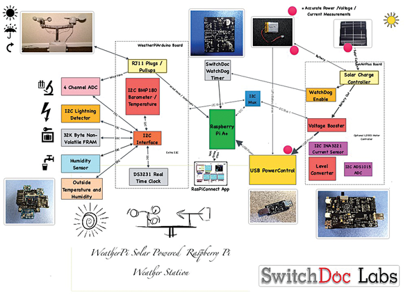 Figure 1: WeatherPi block diagram.
The WeatherPi power subsystem uses a SunAirPlus [4] solar power controller, which handles the solar panels and battery charging and supplies 5V to the Raspberry Pi and the rest of the system (see the "Parts List" box). It also contains sensors that tell you the voltage and current produced by the solar panels and consumed by the batteries and Raspberry Pi, a hardware watchdog timer [5], and a USB PowerControl board that shuts off the power to the Raspberry Pi during a brownout event (after the Raspberry Pi shuts down gracefully under software control).
Parts List
No project is complete without a parts list. These are suggestions! For a number of these boards, you have many options. If you substitute, make sure you check for compatibility.
The sensor subsystem uses a WeatherPiArduino – a second-generation version of the board I wrote about in an earlier issue of the Raspberry Pi Geek [18] – as the base unit and hosts a number of optional sensors (e.g., wind speed/direction, rain/lightning detection, inside/outside temperature and humidity, barometric pressure). Moreover, you can add other sensors to the I2C bus and analog-to-digital (AD) converter, such as UV, dust count, and light color, to sense some types of pollution. (See the "I2C Bus Issues" box.). I will discuss the lightning detection system in this article.
I2C Bus Issues
WeatherPi makes extensive use of the I2C bus on the Raspberry Pi. SwitchDoc Labs loves data and loves I2C devices. Project Curacao has a total of 12 devices, WeatherPi has 11 devices, and SunRover (a solar-powered rover under development at SwitchDoc Labs to appear in Raspberry Pi Geek in fall 2015) will have more than 20 devices and require one I2C bus just to control the motors.
I am always running into I2C addressing conflicts. Because device addresses do not have to be unique, multiple devices often share the same address, and you are just out of luck – without a lot of jimmy rigging – if you have to run both devices on the same I2C.
To get around this addressing problem (specifically the conflict between an INA3221 and the inside humidity sensor and the two identical lightning sensors), I added a bus multiplexer (Figure 2) that allows the addition of more devices on the I2C bus [19], regardless of addressing conflicts (Table 1).
Listing 1 shows what the I2C bus looks like on the Raspberry Pi; it is the output from test software [20] for the I2C four-channel mux (hence, the four independent buses shown for the I2C bus). Note that WeatherPi uses bus 0, bus 1, and bus 2. Bus 2 is only used to connect to the external MOD-1016 lightning detector.
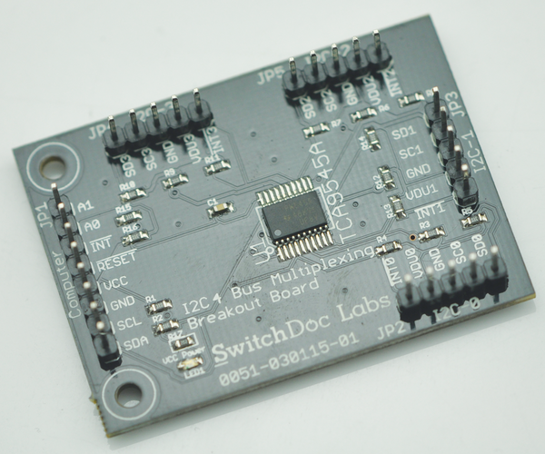 Figure 2: Four-channel multiplexed I2C breakout board.
Table 1
The iPad and its Competitors
| Module | Address | I2C Mux Bus # |
|---|---|---|
| BMP180 barometric pressure |
0x77 |
Bus 0 |
| DS3231 real-time clock |
0x68 |
Bus 0 |
| ATC EEPROM |
0x56 (or 0x57) |
Bus 0 |
| ADS1015 AD converter |
0x49 |
Bus 0 |
| FRAM non-volatile storage |
0x50 |
Bus 0 |
| ADS1015 on SunAirPlus |
0x48 |
Bus 1 |
| INA3221 three-channel voltage/current monitor on SunAirPlus |
0x40 |
Bus 1 |
| MOD-1016 lightning detector |
0x03 |
Bus 0 |
| MOD-1016 lightning detector |
0x03 |
Bus 2 |
| AM2315 outdoor temp/humidity |
0x5C |
Bus 1 |
| I2C four-channel bus mux |
0x73 |
All buses |
| HTU21D-F humidity sensor |
0x40 |
Bus 0 |
Listing 1
I2C Mux Breakout Board Test Output
Test SDL_Pi_TCA9545 Version 1.0 - SwitchDoc Labs
Sample uses 0x73
Program Started at:2015-05-19 02:45:59
-----------BUS 0-------------------
addr = 0x73 returndata = 0x81
tca9545 control register B3-B0 = 0x1
ignore Interrupts if INT3' - INT0' not connected
tca9545 control register Interrupts = 0x8
     0  1  2  3  4  5  6  7  8  9  a  b  c  d  e  f
00:          03 -- -- -- -- -- -- -- -- -- -- -- --
10: -- -- -- -- -- -- -- -- -- -- -- -- -- -- -- --
20: -- -- -- -- -- -- -- -- -- -- -- -- -- -- -- --
30: -- -- -- -- -- -- -- -- -- -- -- -- -- -- -- --
40: 40 -- -- -- -- -- -- -- -- 49 -- -- -- -- -- --
50: 50 -- -- -- -- -- 56 -- -- -- -- -- -- -- -- --
60: -- -- -- -- -- -- -- -- 68 -- -- -- -- -- -- --
70: -- -- -- 73 -- -- -- 77
-----------------------------------
-----------BUS 1-------------------
addr = 0x73 returndata = 0xa2
tca9545 control register B3-B0 = 0x2
ignore Interrupts if INT3' - INT0' not connected
tca9545 control register Interrupts = 0xa
     0  1  2  3  4  5  6  7  8  9  a  b  c  d  e  f
00:          -- -- -- -- -- -- -- -- -- -- -- -- --
10: -- -- -- -- -- -- -- -- -- -- -- -- -- -- -- --
20: -- -- -- -- -- -- -- -- -- -- -- -- -- -- -- --
30: -- -- -- -- -- -- -- -- -- -- -- -- -- -- -- --
40: 40 -- -- -- -- -- -- -- 48 -- -- -- -- -- -- --
50: -- -- -- -- -- -- -- -- -- -- -- -- -- -- -- --
60: -- -- -- -- -- -- -- -- -- -- -- -- -- -- -- --
70: -- -- -- 73 -- -- -- --
-----------------------------------
-----------BUS 2-------------------
addr = 0x73 returndata = 0x84
tca9545 control register B3-B0 = 0x4
ignore Interrupts if INT3' - INT0' not connected
tca9545 control register Interrupts = 0x8
     0  1  2  3  4  5  6  7  8  9  a  b  c  d  e  f
00:          03 -- -- -- -- -- -- -- -- -- -- -- --
10: -- -- -- -- -- -- -- -- -- -- -- -- -- -- -- --
20: -- -- -- -- -- -- -- -- -- -- -- -- -- -- -- --
30: -- -- -- -- -- -- -- -- -- -- -- -- -- -- -- --
40: -- -- -- -- -- -- -- -- -- -- -- -- -- -- -- --
50: -- -- -- -- -- -- -- -- -- -- -- -- -- -- -- --
60: -- -- -- -- -- -- -- -- -- -- -- -- -- -- -- --
70: -- -- -- 73 -- -- -- --
The software subsystem of WeatherPi runs in Python on the Raspberry Pi. It collects data, stores it in a MySQL database, builds graphs, and does housekeeping and power monitoring.
The power system in WeatherPi comprises four parts:
The two 3.4W solar panels are high-quality panels I have used in previous projects and last a long time, even in the tropical sun. Figure 3 shows the same panels used in Project Curacao after six months in the sun. The reflections are clouds, not dirt.
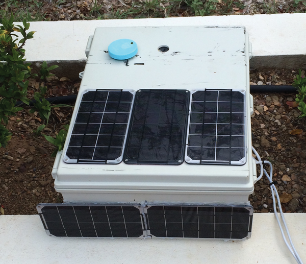 Figure 3: Project Curacao solar panels.
The SunAirPlus solar power controller includes an I2C INA3221 three-channel current/voltage monitor and a I2C four-channel, 12-bit AD converter (ADS1015). The INA3221 allows you to monitor all of the major currents and voltages in the system (battery/solar panels/load, computer ), so you can tell what your solar power project is doing in real time.
Listing 2 is the results from the SunAirPlus board test program [21] using the onboard INA3221. You can see that the battery is almost fully charged and the solar cell voltage (actually a variable-power supply on the test bench) is 5.19V supplying 735mA. You can use this board to power your projects and add a servo or stepper motor to track the sun with the use of photoresistors to generate even more power [22].
Listing 2
INA3221 Test Output
Test SDL_Pi_INA3221 Version 1.0 - SwitchDoc Labs
Sample uses 0x40 and SunAirPlus board INA3221
Will work with the INA3221 SwitchDoc Labs Breakout Board
------------------------------
LIPO_Battery Bus Voltage: 4.15 V
LIPO_Battery Shunt Voltage: -9.12 mV
LIPO_Battery Load Voltage: 4.14 V
LIPO_Battery Current 1: 91.20 mA
Solar Cell Bus Voltage 2: 5.19 V
Solar Cell Shunt Voltage 2: -73.52 mV
Solar Cell Load Voltage 2: 5.12 V
Solar Cell Current 2: 735.20 mA
Output Bus Voltage 3: 4.88 V
Output Shunt Voltage 3: 48.68 mV
Output Load Voltage 3: 4.93 V
Output Current 3: 486.80 mA
The USB PowerController board is basically a controlled solid state relay to turn the power on and off to the Raspberry Pi. This board sits between the solar power controller (SunAirPlus) and a Raspberry Pi Model A+. The input to the board was designed to come directly from a LiPo battery, so the computer won't be turned on until the LiPo battery has charged to above ~3.8V. A hysteresis circuit makes sure the board won't turn on and immediately off again because the power supply is yanked down when the computer turns on (putting a load on the battery). This really happens, and you kill Raspberry Pi SD cards this way.
The Raspberry Pi will lose WiFi connection periodically if you are using certain inexpensive WiFi USB dongles. For a system like WeatherPi (which is designed to stay up indefinitely – although I reboot every 48 hours to make sure!), this can be a problem. The system seems to lose connectivity every couple of days, even with a cron job pinging the router every 10 minutes. I know the computer and software are still running, because I can see the GP1 light flash on the SunAirPlus board (which is toggled every 15 seconds by the WeatherPi software); after rebooting, I can see that the database also has no gaps in the data.
The Raspberry Pi is running, but the WiFi adaptor has quit. To fix this, I now make a network connectivity check (Listing 3) every 30 minutes in the main WeatherPi Loop. The check tries to reset the WiFi adaptor three times; then, if that fails, it reboots the Raspberry Pi. Using this routine every 30 minutes seems to have fixed the problem. I might still have gaps in coverage, but now they are limited to 30 minutes in most cases and two hours at most.
Listing 3
WLAN_check()
01 WLAN_check_flg = 0
02
03 def WLAN_check():
04   '''
05   This function checks if the WLAN is still up by pinging the router.
06   If there is no return, we'll reset the WLAN connection.
07   If the resetting of the WLAN does not work, we need to reset the Pi.
08   source http://www.raspberrypi.org/forums/viewtopic.php?t=54001&p=413095
09   '''
10   global WLAN_check_flg
11   ping_ret = subprocess.call(['ping -c 2 -w 1 -q 192.168.1.1 |grep "1 received" > /dev/null 2> /dev/null'], shell=True)
12   if ping_ret:
13       # we lost the WLAN connection.
14       # did we try a recovery already?
15       if (WLAN_check_flg>2):
16           # we have a serious problem and need to reboot the Pi to recover the WLAN connection
17           print "logger WLAN Down, Pi is forcing a reboot"
18           pclogging.log(pclogging.ERROR, __name__, "WLAN Down, Pi is forcing a reboot")
19           WLAN_check_flg = 0
20           rebootPi("WLAN Down")
21           #subprocess.call(['sudo shutdown -r now'], shell=True)
22       else:
23           # try to recover the connection by resetting the LAN
24           #subprocess.call(['logger "WLAN is down, Pi is resetting WLAN connection"'], shell=True)
25           print "WLAN Down, Pi is trying resetting WLAN connection"
26           pclogging.log(pclogging.WARNING, __name__, "WLAN Down, Pi is resetting WLAN connection" )
27           WLAN_check_flg = WLAN_check_flg + 1 # try to recover
28           subprocess.call(['sudo /sbin/ifdown wlan0 && sleep 10 && sudo /sbin/ifup --force wlan0'], shell=True)
29   else:
30       WLAN_check_flg = 0
31       print "WLAN is OK"
As with most projects, I tend to breadboard the circuitry before I put it into the enclosure. With WeatherPi, I spread out the parts, wired them up, made sure each of the major paths worked, and then started placing them in the box, attaching them with screws and posts through the plastic (Figure 4).
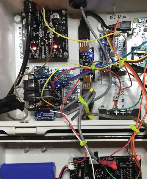 Figure 4: The WeatherPi in its enclosure. The MOD-1016 breakout board is in the center of the figure, which turned out not to be a good location, as discussed later in the article.
Putting the WeatherPi into the BUD Industries box was pretty straightforward. I chose to put the solar power circuit in the top part and the Raspberry Pi and WeatherPiArduino sensor array in the bottom part of the box. After all the elements were placed, I sealed the screw holes and outside screws with silicon caulking.
In building the WeatherPi solar-powered weather station, I saw a couple of parts that I decided would be good candidates for 3D printing. In the six months since I bought the SwitchDoc Labs MakerBot Replicator, I have completely changed the way I build special parts for prototyping. With the latest extruder and firmware updates, the MakerBot rocks!
I have completed 10 long prints with no problems. Instead of Xacto knives and foam, wood, and glue, I now just 3D-print new parts when I need them. The four parts I have 3D printed so far are:
The OpenSCAD files for the bracket and sun cover [23] and for the pylon [24] are available online.
Pages: 8
US / Canada
UK / Australia

Take your first steps in building a solar-powered robot.

How much extra power can a solar panel collect by tracking the sun? SwitchDoc Labs puts it to the test.

A Raspberry Pi Camera module and a diagnostics system allows SunRover to see and check that all systems are go.

We take you step by step through the process of designing and manufacturing a new breakout board product.

Putting power in your robot is more than just running wires – you'll need to make sure the power supply doesn't cause interference that will disrupt other components. This article explores the problem of electrical noise and describes the design for a multiplexing solar power system.

Price $15.99
(incl. VAT)