SunRover Part 2 – Solar Power Controller/Power System
In the previous issue of Raspberry Pi Geek, I introduced the SunRover project. SunRover is a solar-powered robot I am building that will transmit environmental information from a remote location. This article will focus on the SunRover power system and some of the problems I faced getting the power system to play nicely with all the electronic components in the SunRover assembly. I'll show how I redesigned the motor power system and then look at the solar power charging system, which, happily, is working perfectly!
What is Sun Rover?
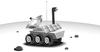
SunRover [1] is a tracked, solar-powered robot designed to move around and explore the area while sending back reports, tracking weather, managing a power budget tightly, and providing a platform for testing new sensors and equipment as they become available. SunRover Robot Philosophy: Yes, I will move around by myself until I get confused or find a cliff. Then I will ask for help from a human. Or at least from a cat.
The major subsystems are shown in Figure 1. SunRover is a big project. The motors, the controllers, the computers, and the sensors are all complex devices in their own right. The current count is 30 for the number of I2C sensors in the project. A block diagram like the one in Figure 1 requires a lot of thought. When you are creating the block diagram, you are actually making design decisions that might be difficult to change later. The SunRover comes with a prebuilt track and motor controller system, two major computer components (a Raspberry Pi 2 for higher levels of control and an Arduino for power management and turning devices and sensors on and off), and dual WiFi communication paths. Solar panels will shift from one subsystem to another according to demand, and the system will use the RasPiConnect control panel application for remote monitoring and control.
[...]
Buy this article as PDF
(incl. VAT)
Buy Raspberry Pi Geek
US / Canada
UK / Australia
Related content
-
SunRover part 1: Track motor controller/power system

Take your first steps in building a solar-powered robot.
-
Building the SunRover navigation system

The Switch Doc continues his effort to build a solar-powered robot. This month the emphasis is on the navigation system.
-
Managing solar power systems with SunAir boards

A successful solar power project requires data analysis and the ability to modify the system to take advantage of prevailing weather conditions.
-
SunRover Part 4 – Adding a Pi Camera and Diagnostics System
A Raspberry Pi Camera module and a diagnostics system allows SunRover to see and check that all systems are go.
-
Protect your electronics from lightning strikes

Add a lightning detector to your vulnerable projects via the I2C bus to protect them from electrical storms.
