Control Rasp Pi slide shows wirelessly
Regular Raspberry Pi Geek readers might recall my "Presentation Machine" story back in 2014 [1]. There, I described how to set up a first generation Raspberry Pi (Rasp Pi) to show slides, with tips on how to use the device during a show. I've since used subsequent versions of the machine at OSCON, Fossetcon, and the Future of Education Technology Conference (FETC).
Today, I look at the evolution of my current Raspberry Pi presentation machine, the "wired" and brand-new ESP8266-based "wireless" clickers, and how it all comes together on stage. I discuss two different pieces of hardware linked together via WiFi, and in a flash of inspiration, I even add a Steampunk theme to the apparatus, resulting in very positive feedback from audiences.
Presentation Machine
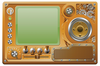
The latest Steampunk Presentation Machine is a Rasp Pi 2 model B (RPi2B) [2] running the latest version of Raspbian Linux with a 32GB Samsung Evo+ microSD card, an Edimax USB WiFi dongle, a Logitech wireless keyboard/mousepad, and the original Logitech C270 webcam (Figure 1). The Rasp Pi is mounted on a frame made out of brass tubing, and an aluminum arm positions the camera. The camera was removed from its original housing and mounted in a custom brass and copper frame, giving it a retro-industrial look (Figure 2). The whole works are mounted on an old piece of laminate flooring.
[...]
Buy Raspberry Pi Geek
US / Canada
UK / Australia
Related content
-
Generation 2 of the Conference Presentation and Manipulation Apparatus
The doctor upgrades a conference slide projection apparatus and adds a retro-clicker with some Python code to keep his talks moving forward.
-
WiFi and the Raspberry Pi

This SwitchDoc column looks at various uses for the inexpensive ESP8266 WiFi/processor combination.
-
Capture temperature data with the ESP8266 and the LM75 Sensor

We use the ESP8266 chip which gathers temperature data from a sensor and then forwards it via REST to a Raspberry Pi, where it's stored in a database.
-
Control your Arduino and Pi projects with a PSP

We create a micro web server on an Arduino and a Raspberry Pi, and then use a PSP web browser to control an airboat.
-
Using the ESP8266 as a micro-controller for servomotors

With an ESP8266 and a few components, you can put together your own robot arm.
