Programming the micro:bit with MicroPython

Lead Image © victor kuznetsov, 123RF.com

Little Bit

The tiny micro:bit single-board computer from the BBC can be used both as an alternative and as a handy companion to the Raspberry Pi. Get started with this simple yet versatile machine.

The Raspberry Pi single-board computer (SBC) and its countless variants can be used for any project imaginable: from learning to code and building a personal server, to exploring the Internet of Things, to building robots. Because it's a computer that runs a full-blown operating system, Raspberry Pi requires some technical skills and effort to master, and it can be overkill for some projects. Of course, Arduino provides a simpler and more approachable physical computing platform. But wouldn't it be great if you could find a device that combines the versatility of Raspberry Pi with the simplicity of Arduino?

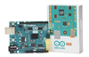
Enter BBC micro:bit [1]. It's probably unfair to call this tiny machine (Figure 1) a mere cross between Raspberry Pi and Arduino, because micro:bit is a unique and innovative device in its own right, and it has several advantages that make it a worthy alternative to both Raspberry Pi and Arduino. The most obvious advantage is the price: At ~£13 (~$17), micro:bit is cheaper than most Raspberry Pi and Arduino models. Unlike Raspberry Pi, you can use micro:bit right out of the box without going through the rigmarole of downloading an image file, burning it onto an SD card, and then booting and configuring the system. This also means it's practically impossible to make micro:bit unbootable or brick the board altogether. Better still, micro:bit has on-board physical buttons, an LED array, and sensors.

Figure 1: Despite its size, BBC micro:bit is a capable and versatile board. This view of the micro:bit shows the back side. The front side has a 5x5 LED array and two programmable buttons.

The board supports the MicroPython dialect of the Python scripting language, so you build simple projects right away with a minimum of effort. Similar to Raspberry Pi, micro:bit features a GPIO port, so it's possible to use the board with sensors, motors, and other devices. Add in low power consumption, and you have a board that can be put to a variety of practical uses. The best part is that you can use a Raspberry Pi to program and manage micro:bit.

First Steps

To get started with micro:bit, you need several additional parts, including a USB data cable, a battery holder, and an edge connector breakout board. Both the battery holder and the breakout board are optional, but they can be useful for many projects. The battery holder allows you to power the micro:bit board with two AAA batteries, and the breakout board makes access to GPIO pins easier.

Although you can use the default web-based coding environment at BBC micro:bit World [2] to write micro:bit scripts, you can also program locally using the dedicated Mu editor [3]. To install it on Raspberry Pi, grab the latest mu.bin binary file from the Mu editor's website and enter:

chmod +x mu.bin
sudo usermod -a -G dialout <username>

The first line makes the file executable, and the second line makes it possible to push scripts to micro:bit directly from the editor. Replace <username> with your actual username (e.g., pi).

With all the pieces in place, connect the Raspberry Pi to the micro:bit board via the micro-USB port, launch the Mu editor, and you are ready to write your first MicroPython script.

MicroPython Basics

The version of MicroPython installed on micro:bit includes the microbit module that provides an API for all the board's hardware components. So all micro:bit scripts should start with the from microbit import * statement that imports the module (Figure 2). Because the board comes with an array of LEDs, you can start with something more interesting than a simple blinking LED as your first project. For example, you can make the LED array display a scrolling text message using the display.scroll() method. The simple script below scrolls the "Oh Hai, World!" text on the LED array:

Figure 2: The Mu editor provides a simple coding environment. It can upload scripts to micro:bit, too.
from microbit import *
display.scroll("Oh Hai, World!")

To scroll this message infinitely, you can add a while loop as follows:

from microbit import *
while True:
    display.scroll("Oh Hai World!")

Paste the code above into a new text file in the Mu editor, save the script, make sure that micro:bit is connected to the Raspberry Pi, and then press the Flash button to compile the script and transfer it to micro:bit. The yellow LED on the micro:bit should blink during the transfer, and once the operation is complete, you should see the message scrolling on the LED array.

The LED array can be used to display simple images, too, and the display.show() method allows you to do just that. Better still, MicroPython comes with a library of ready-made images for use in your scripts. This library includes faces, arrows, and objects that you can integrate into your scripts. Displaying an image is as easy as specifying it in the display.show() routine; for example:

display.show(Image.MEH)
display.show(Image.UMBRELLA)

Each LED in the array can be controlled individually using the display.set_pixel method that requires three values: pixel row, pixel column, and pixel brightness. So the

display.set_pixel(2, 2, 9)
display.set_pixel(2, 2, 0)

commands, for example, set the brightness of the middle LED (rows and columns are numbered 0 through 4) to the maximum level in the first line (thus turning the LED on) and to the minimum level in the second line (thus turning the LED off). The script in Listing 1 [4] demonstrates how the display.set_pixel() routine can be used to control individual LEDs.

Listing 1

Controlling Individual LEDs

01 from microbit import *
02 from random import randint
03 while True:
04     val = 9
05     x = randint(0, 4)
06     y = randint(0,4)
07     display.set_pixel(x, y, val)
08     while (val > 0):
09         display.set_pixel(x, y, val)
10         sleep(500)
11         val = val-1
12         display.set_pixel(x, y, 0)

The script uses the randint method to generate random numbers – between 0 and 4 in this case. These numbers are then used to specify pixel position. The val variable determines the brightness level, and it's set to 9 from the start. The while (val > 0) loop uses the val variable as a counter gradually to reduce the LED's brightness and then turn it off. Flash the script to micro:bit, and you should see random LEDs turning on and gradually fading away.

The micropython module identifies the two physical on-board buttons as button_a and button_b, and it has three button-related methods. The first one is the button.is_pressed() routine that returns True if the button is pressed and returns False otherwise. The script in Listing 2 illustrates how this method works. When button A is pressed for half a second, the middle LED turns on; otherwise it stays off.

Listing 2

Programmable Buttons

01 from microbit import *
02
03 while True:
04     sleep(500)
05     if button_a.is_pressed():
06         display.set_pixel(2, 2, 9)
07         sleep(1000)
08     else:
09         display.set_pixel(2, 2, 0)

The other two button-related methods are button.was_pressed() (returns True if the button was pressed since the device booted or the last time the method was called) and button.get_presses() (returns the total number of times the button was pressed).

In addition to the LED array and buttons, micro:bit also features a compass and an accelerometer, and the microbit module has several methods for accessing both components. The accelerometer.get_x(), accelerometer.get_y(), and accelerometer.get_z() methods return acceleration measurements in the x, y, and z axes as integer numbers. Using these methods, you can whip up a simple script like that in Listing 3 to transform micro:bit into a no-frills digital level.

Listing 3

Accelerometer

01 from microbit import *
02
03 while True:
04     x = accelerometer.get_x()
05     if x > 50:
06         display.show(Image.ARROW_W)
07     elif x < -50:
08         display.show(Image.ARROW_E)
09     else:
10         display.show(Image.TARGET)

The script reads the x-axis measurements, and depending on the obtained values, the LED array displays the appropriate arrow images that help you level the board. When the board is leveled, the LED array shows an image that looks like a target. The default 50 and -50 reference values control the level's sensitivity. Increase the values to make the level less sensitive and decrease to boost sensitivity.

The accelerometer also supports basic gestures, such as "up", "down", "left", "right", "face up", "face down", and "shake", and the accelerometer.current_gesture() method can be used to detect these gestures. The code in Listing 4 displays the butterfly image when you shake the board.

Listing 4

The "shake" Gesture

01 from microbit import *
02
03 while True:
04     gesture = accelerometer.current_gesture()
05     if gesture == "shake":
06         display.show(Image.BUTTERFLY)
07     else:
08         display.show(Image.ASLEEP)

The strips at the bottom of the micro:bit board are not decorations: They are GPIO pins. The micro:bit has 25 GPIO connectors, and five of them are wider than the others and have holes, which makes it easier to use them with banana plugs and crocodile clips. The pins labeled 0, 1, and 2 on the front side of the board (in Figure 1, the first three holes, left to right) are digital pins with analog-to-digital converters (ADCs), which means that they can be used with various analog devices and sensors – something you can't do with Raspberry Pi without additional work. If you are familiar with the GPIO on Raspberry Pi, you won't have problems using GPIO pins on micro:bit, and the microbit module provides several methods for working with pins. These include pin.is_touched() (returns True if the pin is in fact touched), pin.read_digital() (reads the digital input of the pin; returns 1 if the pin is high, and 0 if it's low), and pin.write_digital() (sets the pin to high or low using the 1 and 0 values). The following script is a simple and fun example of using micro:bit's GPIO pin:

from microbit import *
while True:
    if pin0.is_touched():
        display.show(Image.SURPRISED)
    else:
        display.show(Image.ASLEEP)

It displays different messages depending on whether it is being touched or not.

Buy this article as PDF

Express-Checkout as PDF

Pages: 6

Price $2.95
(incl. VAT)

Buy Raspberry Pi Geek

SINGLE ISSUES
 
SUBSCRIPTIONS
 
TABLET & SMARTPHONE APPS
Get it on Google Play

US / Canada

Get it on Google Play

UK / Australia

Related content

  • The Pi Wire

    Arduino’s “Invent Your Future” Contest; Fedora for Rasp Pi; New Raspberry Pi Kits for Windows IoT Core; micro:bit Education Foundation.

  • News

    Google bring AI to Raspberry Pi, Raspberry Pi Zero W board, British invasion: micro:bit comes to Adafruit, and more news from around the globe!

  • Welcome

    Our cover says "Boards Galore!", and we're not kidding. Last issue, we reviewed the LeMaker HiKey and the Banana Pi M3. This issue we add the Odroid-C2, Pine A64+, LeMaker Guitar, BBC micro:bit, and C.H.I.P. Each of these small-board computers (SBCs) have strengths and weaknesses, so you have to understand the needs of your project to choose wisely.

  • New Products

    What's new in the SBC, IoT, and maker realm.

  • Diving Deep

    The past year has seen a continued emphasis on STEM (science, technology, engineering, and mathematics) education in English-speaking countries.